Character Movement Link to heading
Character Movement is a system that provides the locomotion system, designed specifically for humanoid characters. Character Movement is an actor component that, when assigned to a character class, grants movement modes such as walking, falling, swimming, and flying. Additionally, it has strong integration with networked gameplay and provides a framework to help developers create custom networked movement.
To integrate Character Movement into a character in your project, you must ensure that the character includes basic animations such as idle, walk, run, and jump. If you’re using the Unreal Mannequin in Fab, you can find free animation packs for this character.
Option 1: Character Class Blueprint Link to heading
First, if you haven’t created a character yet, create one. Its parent class must inherit from Character. Right-click on an empty space in your Content Browser, inside the folder where you want to save your character, then select Blueprint Class and afterward, select Character.
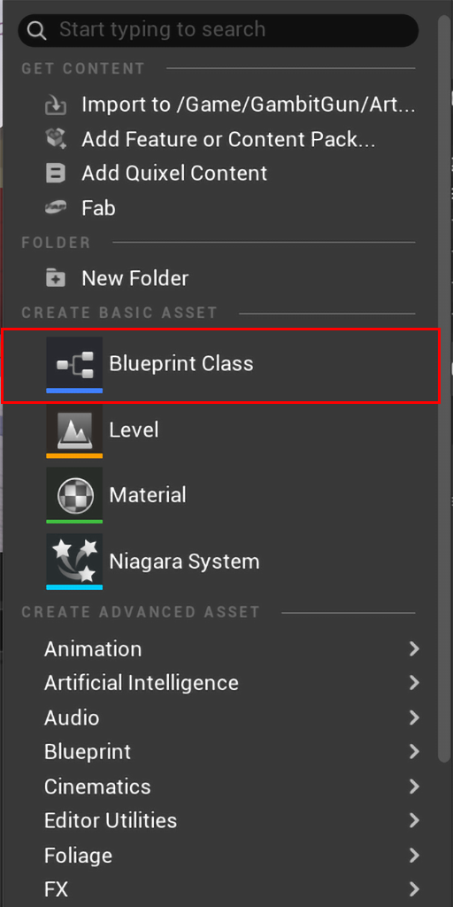
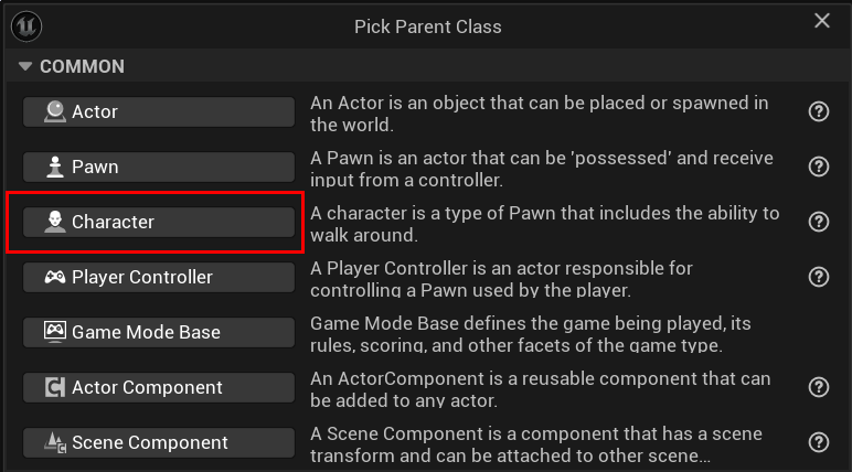
A Character is a type of pawn that includes the ability to walk around.
Option 2: C++ Character Class Link to heading
We can create the character using our own C++ class. To do this, we first need to create a C++ class that inherits from Character. In your Content Browser, navigate to the C++ folders and go to the folder where you want to save your character. Right-click on an empty space and then select New C++ Class.
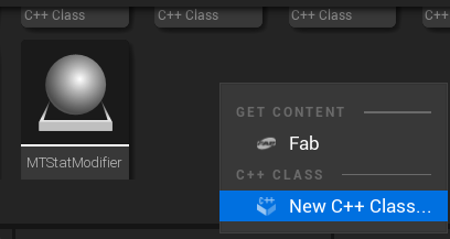
Our class must inherit from Character. After selecting Character, click Next.
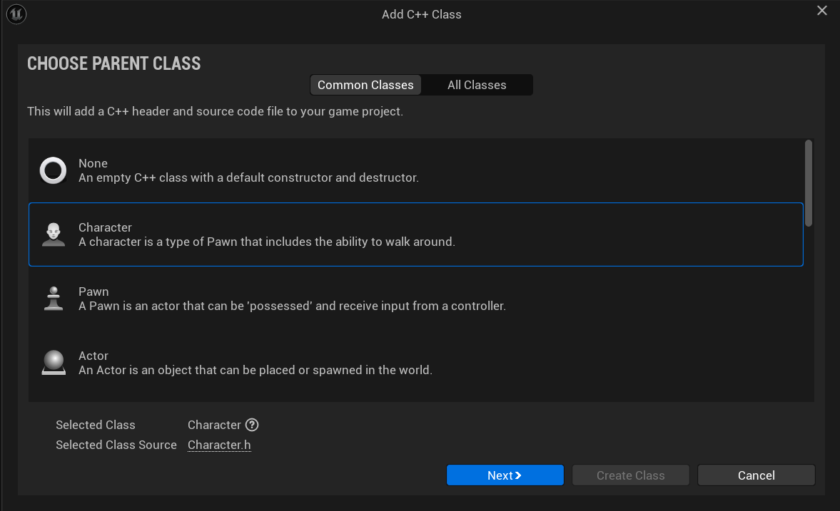
Name your class like you want, then click Create Class and wait for Unreal to compile the new class.
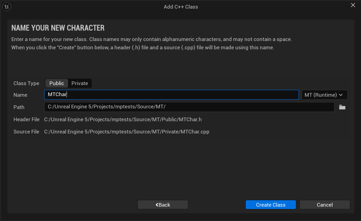
Once you have your class, go back to the content folders of your project. In the location where you want to create your character, right-click on an empty space and select Blueprint Class.
Now, instead of selecting the Character option, use the search bar at the bottom of the window to find the C++ class you previously created, then click Select.
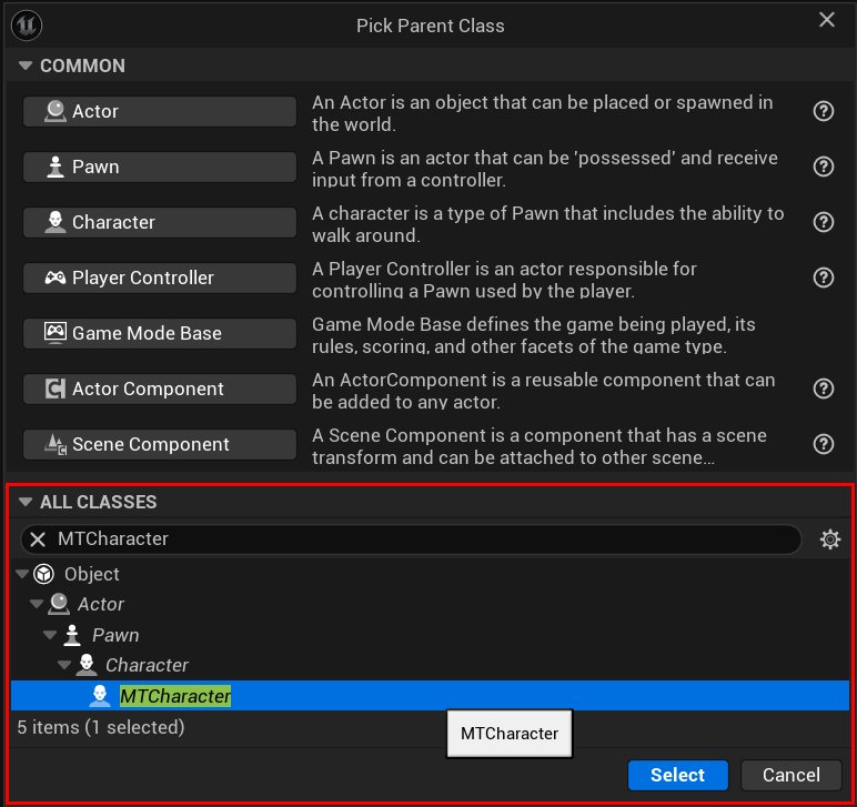
In the C++ class, we need to declare the components that our character will use. In this case, in the .h file of our class, we will declare the Spring Arm Component and the Camera Component.
UPROPERTY(VisibleAnywhere, BlueprintReadOnly, Category = Camera, meta = (AllowPrivateAccess = "true"))
USpringArmComponent* CameraBoom;

UPROPERTY(VisibleAnywhere, BlueprintReadOnly, Category = Camera, meta = (AllowPrivateAccess = "true"))
UCameraComponent* FollowCamera;
Now, in the .cpp file, we will include the following class libraries.
#include "Camera/CameraComponent.h"
#include "GameFramework/SpringArmComponent.h"
#include "GameFramework/CharacterMovementComponent.h"
In the AYourCreatedClass::AYourCreatedClass constructor method declare the following
CameraBoom = CreateDefaultSubobject<USpringArmComponent>(TEXT("CameraBoom"));
CameraBoom->SetupAttachment(RootComponent);
CameraBoom->TargetArmLength = 400.0f; // The camera follows at this distance behind the character
CameraBoom->bUsePawnControlRotation = true; // Rotate the arm based on the controller

FollowCamera = CreateDefaultSubobject<UCameraComponent>(TEXT("FollowCamera"));
FollowCamera->SetupAttachment(CameraBoom, USpringArmComponent::SocketName); // Attach the camera to the end of the boom and let the boom adjust to match the controller orientation
FollowCamera->bUsePawnControlRotation = false; // Camera does not rotate relative to arm

GetCharacterMovement()->bOrientRotationToMovement = true; // Character moves in the direction of input...
From here, you can continue regardless of the option you have chosen.
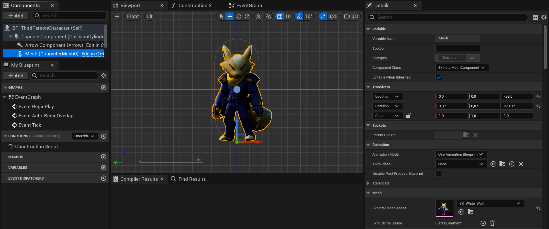
Double-click your Blueprint Character to open its class defaults, then in the components tab select the Mesh(CharacterMesh0) Skeletal Mesh Component, and navigate to the Details panel.
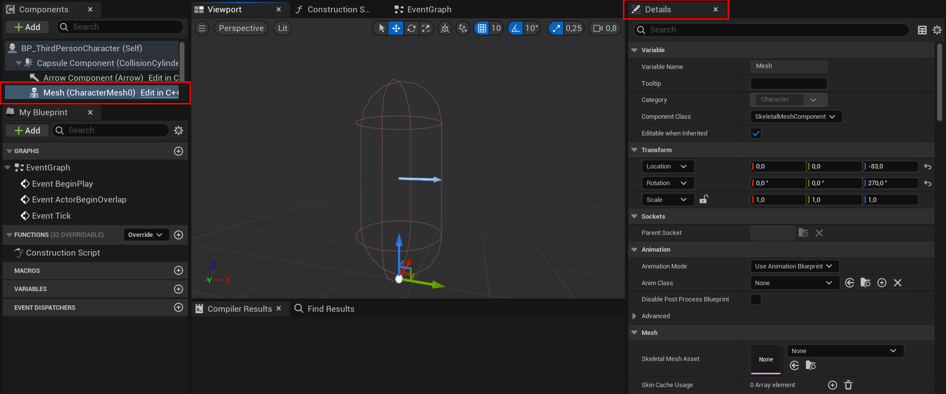
In the Mesh category, select the dropdown under Skeletal Mesh and choose the Skeletal Mesh of your character.
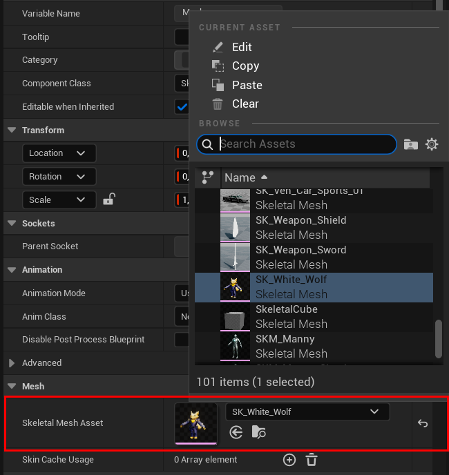
In the Details panel, navigate to the Transform category, and set the Mesh’s Location and Rotation so that the feet or the lowest part of your character align with the bottom of the capsule, and the highest part of the character corresponds to the top of the capsule.
The values you will see below might not be the same for your character. If you’re using the default mannequin, the values that work best in that case are:
- Transformation (0, 0, -90).
- Rotation (0, 0, -90).
You can also adjust the Capsule Half Height and Capsule Radius values if your character is larger or smaller than the default model (Unreal Mannequin).
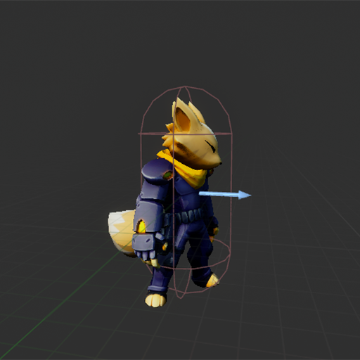
Your character’s Skeletal Mesh will now be oriented in the direction of the forward-facing Arrow Component as follows:
The next step is to add a camera for the character. To do this, the first thing we will add is a Spring Arm Component, and it should be a child of the Skeletal Mesh. With the SK selected, you can either add the component directly or simply add the component and then drag it to the SK to make it a child of the SK.
We will do the same with the character’s camera; add the component, and the camera should be a child of the Spring Arm.
Spring Arm Configuration Link to heading
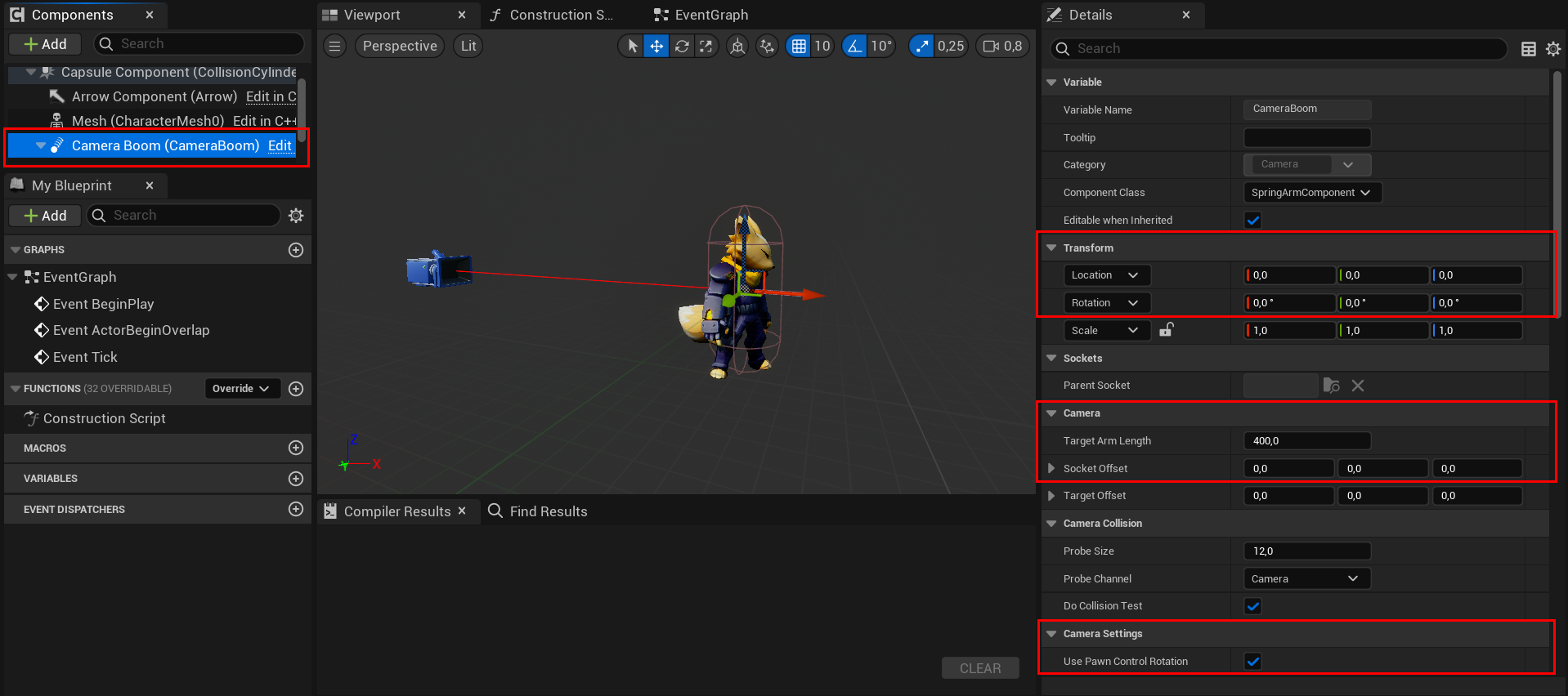
With the Spring Arm selected, you can adjust the Translation and Rotation values, as well as the Target Arm Length and Socket Offset. The values may vary depending on what you’re aiming for or the character you’re using. However, if you’re using the default mannequin and simply want to add a camera without further adjustments, you can try these values for your Spring Arm:
- In the Camera category, set the Socket Offset to (0, 0, 30).
- Navigate to the Transform category and set the Spring Arm Location to (0, 0, 50).
Navigate to the Details panel, and in the Camera Settings category enable the Use Pawn Control Rotation. Enabling use Pawn Control rotation will rotate the camera relative to the spring arm.
Character Movement Setup Link to heading
In the Character Movement: Walking category enable the Ignore Base Rotation variable.
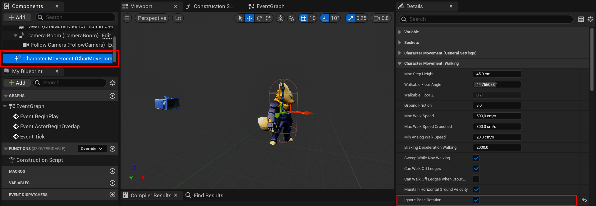
Setting Ignore base rotation to true will tell the character to maintain its current world rotation, and ignore any changes in rotation of the base it’s standing on.
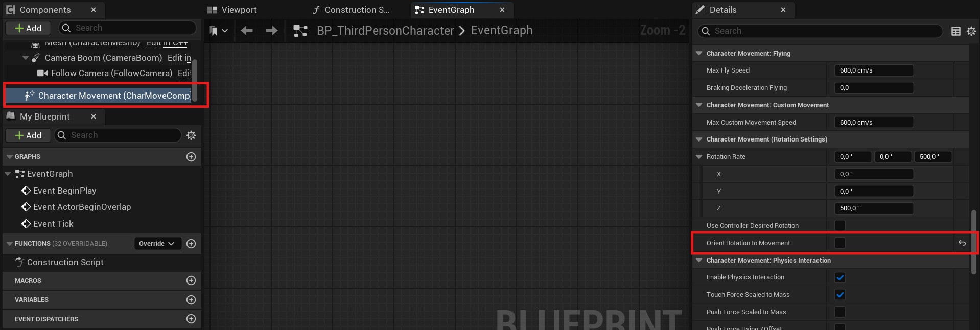
With the Character Movement Component selected, look for the options Use Controller Desired Rotation and Orient Rotation to Movement. Enable or disable them according to your character’s requirements. For this example, they will remain disabled.
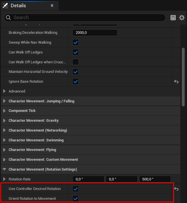
Use Controller Desired Rotation: If true, smoothly rotate the Character toward the Controller’s desired rotation (typically Controller->ControlRotation), using RotationRate as the rate of rotation change. Overridden by OrientRotationToMovement. Normally you will want to make sure that other settings are cleared, such as bUseControllerRotationYaw on the Character.
If true, rotate the Character toward the direction of acceleration, using RotationRate as the rate of rotation change. Overrides UseControllerDesiredRotation. Normally you will want to make sure that other settings are cleared, such bUseControllerRotationYaw on the character
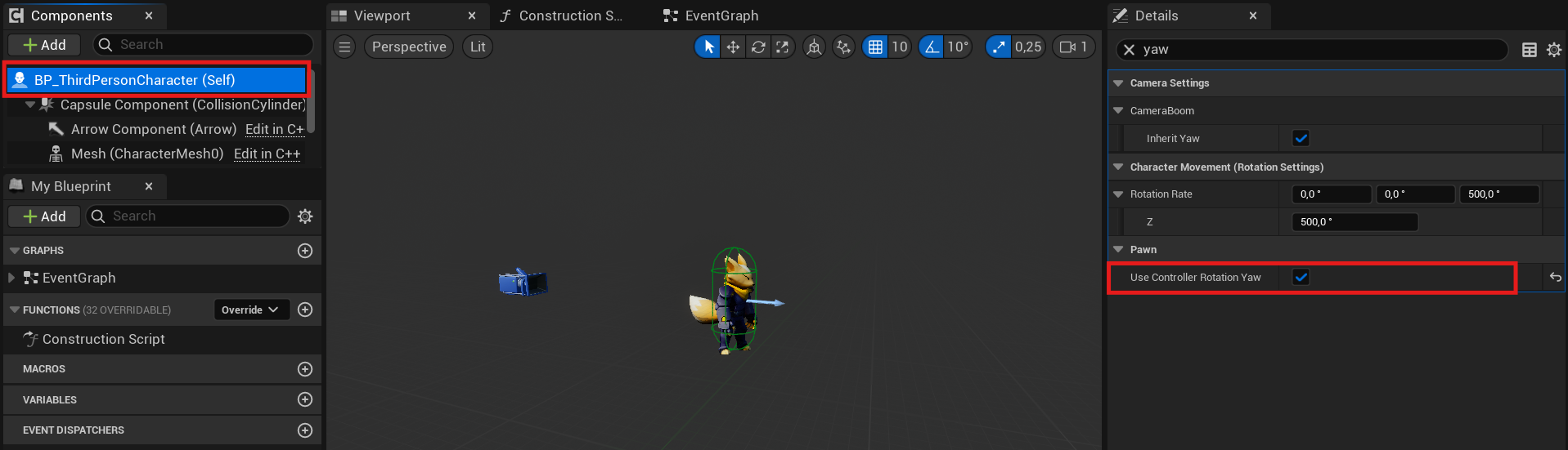
If true, The Pawn’s yaw will be updated to match the Controller’s ControlRotation yaw, if controlled by a PlayerController
Add Inputs Link to heading
Input Actions can be several different types that will determine their behavior. You can make a simple boolean action or a more complex 3D axis. The type of action determines the value. Boolean actions have a simple bool value, an Axis1D is a float value, an Axis2D is an FVector2D, and Axis3D is a whole FVector.
You should use bool actions for inputs that have an on or off state. This is the equivalent of the older Action mappings in the legacy input system. For controls like gamepad thumbstick values, you can use 2D axis actions to hold the X and Y value of the thumbstick position. You can use the 3D axis to hold more complex data, such as motion controller information.
To move around the world with our character, we need to create inputs using Enhanced Input system.
In a separate folder or wherever you prefer to create them, in your Content Browser right-click on an empty space and create four Input Actions: “IA_Move,” “IA_Look,” “IA_Jump,” and “IA_Crouch.”
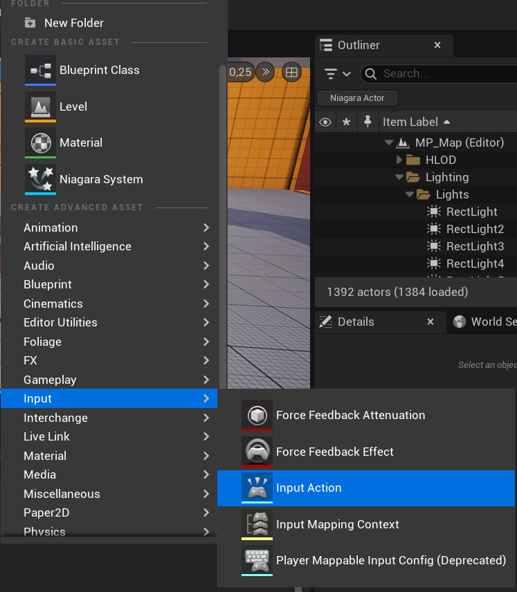
Once you have created them, open your Input Action “IA_Look.”
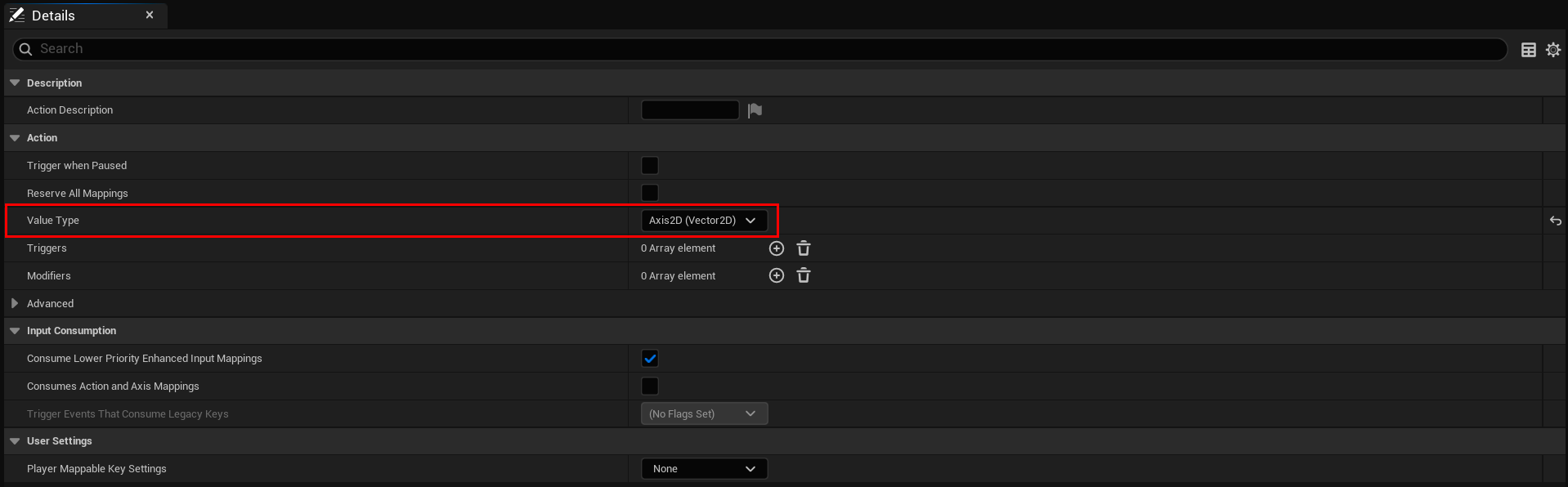
Since we will be rotating the character’s camera along two axes, select Axis2D (Vector2D). This Input Action will receive the X and Y values from the assigned input.
For “IA_Move,” we will also change the Value Type to Axis2D (Vector2D).
Create two more Input Actions, Jump and Crouch. Their Value Type will remain as Digital (bool) for both.
The next step is to create an Input Mapping Context.
To do this, right-click on an empty space in your Content Browser, navigate to Input, and then click on Input Mapping Context.
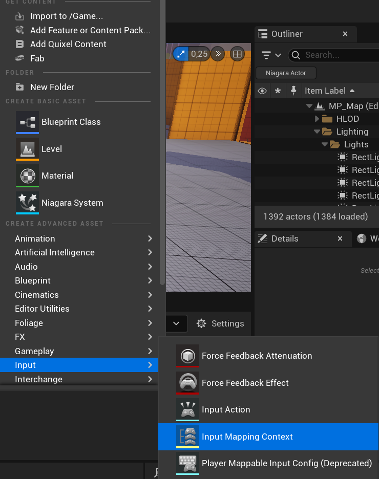
The basic structure of an Input Mapping Context is a hierarchy with a list of Input Actions at the top level. Under the Input Action level is a list of user inputs that can trigger each Input Action, such as keys, buttons, and movement axes.
The bottom level contains a list of Input Triggers and Input Modifiers for each user input, which you can use to determine how an input’s raw value is filtered or processed, and what restrictions it must meet in order to drive the Input Action at the top of its hierarchy.
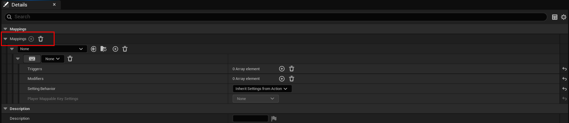
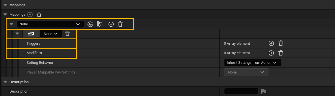
Now we have the following options:
Set Input Action: Select one of the Input Actions we created.
Set the key value: Choose any key from your keyboard or gamepad to trigger your Input Action.
Triggers: Input Triggers determine if user input, after optional Input Modifiers, should activate the corresponding Input Action in its Input Mapping Context. Most triggers analyze input for minimum actuation, short taps, holds, or press/release events. The exception is the “Chorded Action” trigger, which activates only with another Input Action.
Modifiers: Modifiers are pre-processors that alter the raw input values that UE receives before sending them on to Input Triggers. The Enhanced Input Plugin has a variety of Input Modifiers to perform tasks like changing the order of axes, implementing “dead zones”, and converting axial input to world space.
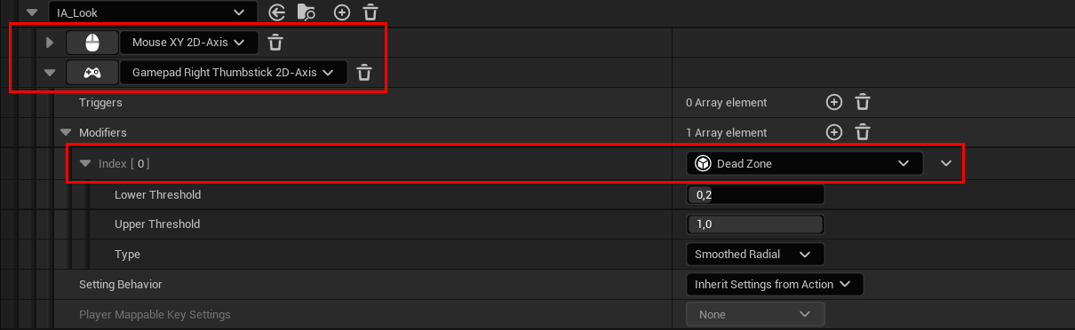
For “IA_Look,” first assign the desired inputs. The usual choices are the mouse, found as Mouse XY 2D-Axis, and the right joystick on a gamepad, found as Gamepad Right Thumbstick 2D-Axis.
Add a Dead Zone modifier. This modifier ensures that values within the range LowerThreshold -> UpperThreshold will be ramped from 0 -> 1. Values outside this range will be clamped.
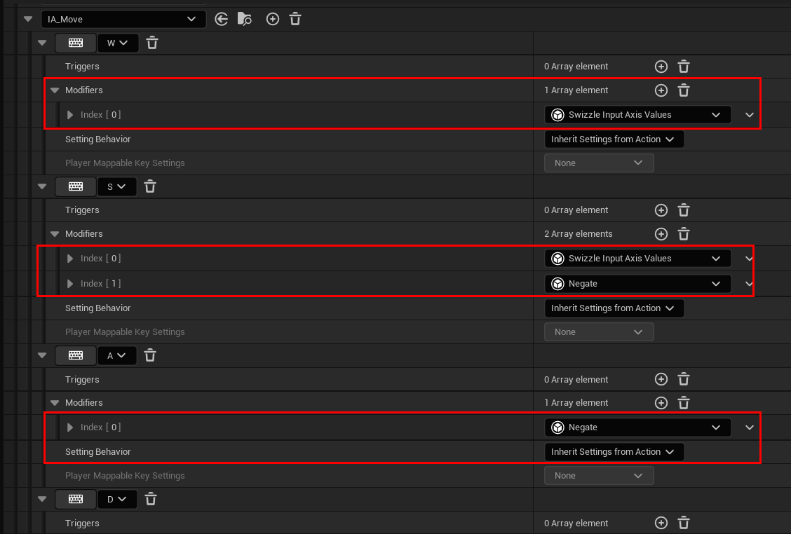
For “IA_Move,” add the inputs as WASD for the keyboard and Gamepad Left Thumbstick 2D-Axis for the gamepad.
On W key, add the Swizzle Input Axis Values modifier. This is useful to map a 1D input onto the Y axis of a 2D action.
On S key, add the Swizzle Input Axis Values modifier and additionally add Negate. Negate inverts the input per axis.
The inputs for moving forward and backward are now set up.
On A key, add the Negate modifier so that the input value is mapped to -X instead of X.
On W key, no modifier is needed.
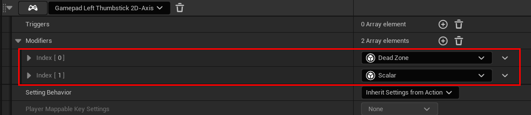
The modifiers required for the gamepad input are Dead Zone and Scalar. This last one scales input by a set factor per axis.
Add “IA_Jump” and assign a key. The usual choice is the spacebar as the jump key. It doesn’t require modifiers or triggers.
The last input for now is for Crouch. Add it to your Input Mapping Context and assign an input. It doesn’t require modifiers or triggers.
Input Triggers Link to heading
Cuando vamos a ejecutar una función desde un input, hay distintos triggers que pueden ejecutar la función. Cada trigger es para un comportamiendo distinto del input.
- Triggered: The action was triggered. This means that it has completed the evaluation of all trigger requirements. For example, a "Press and Release" trigger is sent when the user releases the key.

- Started: An event occurred that began trigger evaluation. For example, the first press of a "Double tap" trigger will call the "Started" state once.

- Ongoing: The trigger is still being processed. For example, a "Press and hold" action is ongoing while the user is holding down the button before the specified duration is reached. Depending on the triggers, this event will fire every tick while the action is evaluated once it receives an input value.

- Completed: The trigger evaluation process is completed.

- Canceled: The triggering was canceled. For example, a user lets go of a button before a "Press and Hold" action can be triggered.
Option 1: C++ Functions for actions Link to heading
In the .h file of the Character, we will declare functions for the character’s actions.
There is a default function for jumping in the character, so it’s not necessary to create its functionality.
/* Called for movement input */
void Move(const FInputActionValue& Value);

/* Called for looking input */
void Look(const FInputActionValue& Value);

/* Called for Crouching input */
UFUNCTION(BlueprintCallable)
void StartCrouch();
void StopCrouching();
Go to your Character’s .cpp file and add the following code.
void AMTCharacter::Move(const FInputActionValue& Value)
{
	// input is a Vector2D
	FVector2D MovementVector = Value.Get<FVector2D>();

	if (Controller != nullptr)
	{
		// find out which way is forward
		const FRotator Rotation = Controller->GetControlRotation();
		const FRotator YawRotation(0, Rotation.Yaw, 0);

		// get forward vector
		const FVector ForwardDirection = FRotationMatrix(YawRotation).GetUnitAxis(EAxis::X);

		// get right vector
		const FVector RightDirection = FRotationMatrix(YawRotation).GetUnitAxis(EAxis::Y);

		// add movement
		if (!bIsCrouched)
		{
			AddMovementInput(ForwardDirection, MovementVector.Y);
			AddMovementInput(RightDirection, MovementVector.X);
		}
	}
}

void AMTCharacter::Look(const FInputActionValue& Value)
{
	// input is a Vector2D
	FVector2D LookAxisVector = Value.Get<FVector2D>();

	if (Controller != nullptr)
	{
		// add yaw and pitch input to controller
		AddControllerYawInput(LookAxisVector.X);
		AddControllerPitchInput(LookAxisVector.Y);
	}
}

void AMTCharacter::StartCrouch()
{
    /* The player will not be able to crouch while falling */
	bool bPlayerFalling = GetMovementComponent()->IsFalling();
	if (not bPlayerFalling)
	{
		Crouch();
	}
}

void AMTCharacter::StopCrouching()
{
	UnCrouch();
}
The reason for creating an event for Crouch and calling another event inside it that actually contains the crouch functionality is because the existing event requires a boolean parameter. It wouldn’t work because BindAction expects to bind functions without parameters or with const FInputActionValue&. If you try to bind a function that receives a bool, it will cause a compilation error.
Enhanced Inputs with C++ Link to heading
In the .h file of the Character, declare the Input Mapping Context where we assign our Input Actions.
/* MappingContext */
UPROPERTY(EditAnywhere, BlueprintReadOnly, Category = Input, meta = (AllowPrivateAccess = "true"))
UInputMappingContext* DefaultMappingContext;
Then, declare all the Input Actions you have created.
/* Move Input Action */
UPROPERTY(EditAnywhere, BlueprintReadOnly, Category = Input, meta = (AllowPrivateAccess = "true"))
UInputAction* MoveAction;

/* Look Input Action */
UPROPERTY(EditAnywhere, BlueprintReadOnly, Category = Input, meta = (AllowPrivateAccess = "true"))
UInputAction* LookAction;

/* Jump Input Action */
UPROPERTY(EditAnywhere, BlueprintReadOnly, Category = Input, meta = (AllowPrivateAccess = "true"))
UInputAction* JumpAction;

/* Crouch Input Action */
UPROPERTY(EditAnywhere, BlueprintReadOnly, Category = Input, meta = (AllowPrivateAccess = "true"))
UInputAction* CrouchAction;
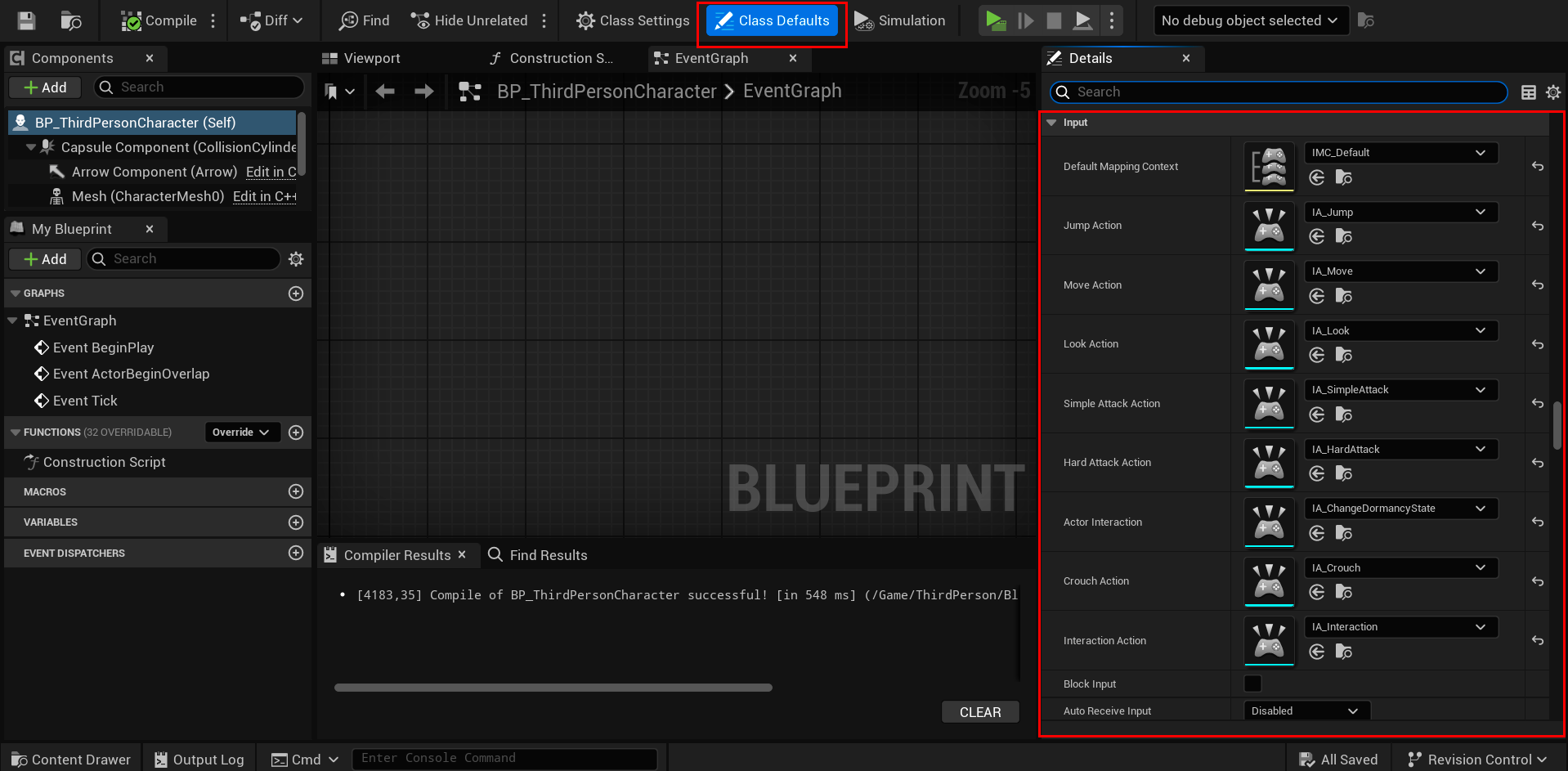
Compile your code and then open your character’s blueprint. Select Class Defaults and then, in your details panel, scroll down to find the “Input” category (or whatever you named the category) and assign your Input Mapping Context and the Input Actions. Compile and save the blueprint.
Back to the code, go to your Character’s .h file and declare the following functions.
virtual void NotifyControllerChanged() override;

virtual void SetupPlayerInputComponent(class UInputComponent* PlayerInputComponent) override;
NotifyControllerChanged: This function runs when the character’s controller changes, ensuring that if a player controls it, the proper input mapping is activated via the Enhanced Input system. It retrieves the input subsystem from the LocalPlayer and adds the input mapping context (DefaultMappingContext), allowing the player to use their controls correctly.
SetupPlayerInputComponent: is used to bind player inputs (movement, actions, etc.) to a character or an input-enabled actor.
Go to your Character’s .cpp file and write the following code for the functions we just declared.
NotifyControllerChanged
void AMTCharacter::NotifyControllerChanged()
{
	Super::NotifyControllerChanged();

	// Add Input Mapping Context
	if (APlayerController* PlayerController = Cast<APlayerController>(Controller))
	{
		if (UEnhancedInputLocalPlayerSubsystem* Subsystem = ULocalPlayer::GetSubsystem<UEnhancedInputLocalPlayerSubsystem>(PlayerController->GetLocalPlayer()))
		{
			Subsystem->AddMappingContext(DefaultMappingContext, 0);
		}
	}
}
SetupPlayerInputComponent
if (UEnhancedInputComponent* EnhancedInputComponent = Cast<UEnhancedInputComponent>(PlayerInputComponent)) {
    // Moving
    EnhancedInputComponent->BindAction(MoveAction, ETriggerEvent::Triggered, this, &AMTCharacter::Move);

    // Looking
    EnhancedInputComponent->BindAction(LookAction, ETriggerEvent::Triggered, this, &AMTCharacter::Look);

    // Jumping
    EnhancedInputComponent->BindAction(LookAction, ETriggerEvent::Triggered, this, &AMTCharacter::Jump);
    EnhancedInputComponent->BindAction(LookAction, ETriggerEvent::Completed, this, &AMTCharacter::StopJumping);

    // Crouching
    EnhancedInputComponent->BindAction(CrouchAction, ETriggerEvent::Started, this, &AMTCharacter::Crouch);
    EnhancedInputComponent->BindAction(CrouchAction, ETriggerEvent::Completed, this, &AMTCharacter::StopCrouching);
}
Let’s take a look at the parameters of BindAction.
(const UInputAction *Action, ETriggerEvent TriggerEvent, AMTCharacter *Object, void (AMTCharacter::Func)())
In the first parameter, assign the name of the Input Action that was previously declared in the
.hfile.In the second parameter, manage the type of Trigger that will handle the Input.
The third parameter,
AMTCharacter *Object, refers to the object instance that will execute the function when the input action is triggered. Usually,thisis used to indicate that the current object will handle the action.In the fourth parameter, place the function that will be executed when the input is triggered.
The way Jump and Crouch work is that by using the Started trigger in the input bindings to the event, pressing the assigned key will execute the function. In the bindings where we use the Completed trigger, releasing the key will execute the function that is set in the binding.
Option 2: Blueprint Functions for actions Link to heading
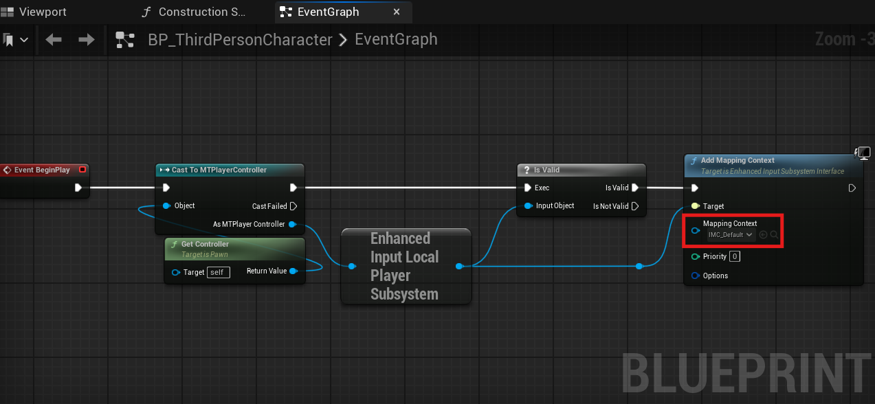
Open your BP Character and add your Input Mapping Context as shown in the image.
In your Begin Play event, cast to PlayerController and connect the GetController function to the input pin of the cast.
Then, drag and drop from the output pin of the PlayerController cast and search for Enhanced Input Local Player Subsystem. Drag and drop from the output pin of this node and search for two more nodes: IsValid and Add Mapping Context.
Finally, add the Input Mapping Context you created to this last node. Make sure everything is connected as shown in the image below.
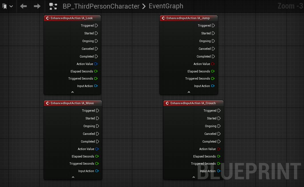
Then, search in your Event Graph for the four inputs you created. Look for them using the exact names you assigned to them.
Jump Input Link to heading
In your Event Graph, search for the Jump and Stop Jumping events. Connect the Started exec pin of the input to the Jump function and the Completed exec pin to the Stop Jumping function.

Crouch Input Link to heading
Just like with Jump, search in your Event Graph for the Crouch and UnCrouch events. Connect the Started exec pin of the input to the Crouch function and the Completed exec pin to the UnCrouch function.

Look Input Link to heading
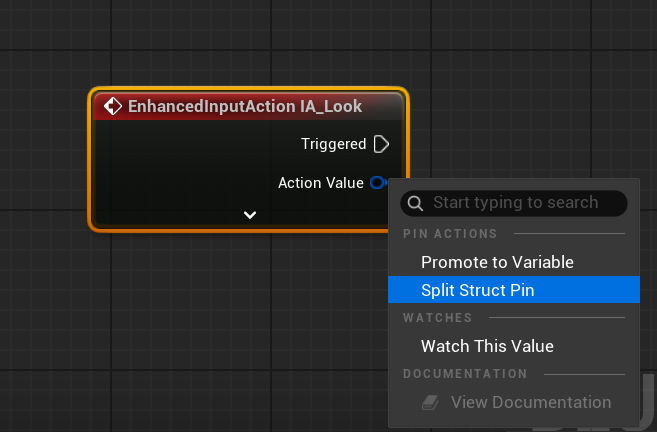
Right-click on the output pin “Action Value” of your Look Input Action and then select Split. This will separate the output pin into two output pins: Axis Value X and Axis Value Y.
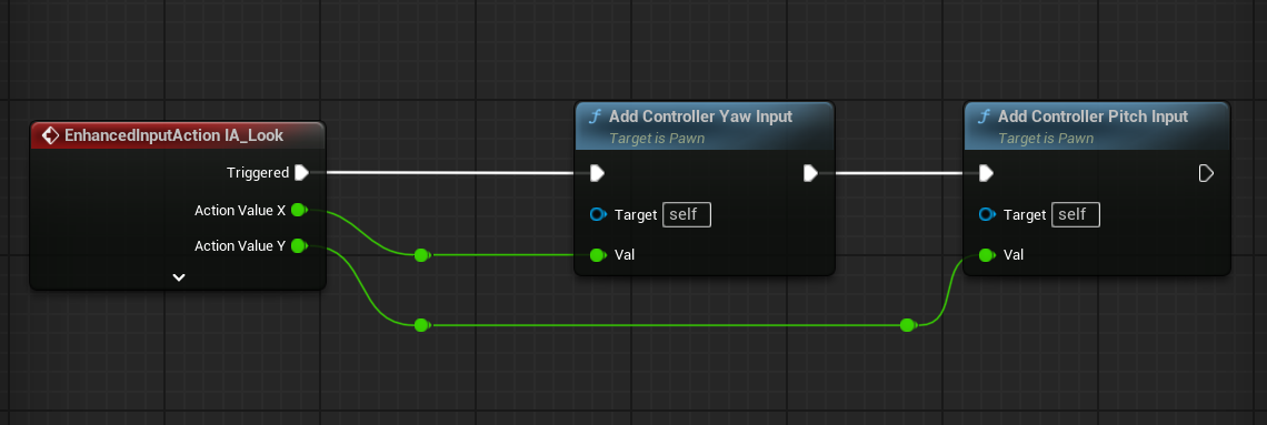
In your Event Graph, search for the nodes “Add Controller Pitch Input” and “Add Controller Yaw Input.” Connect the Axis Value X output pin of your Input Action to Add Controller Pitch Input and the Axis Value Y output pin to Add Controller Yaw Input, as shown below.
Move Input Link to heading
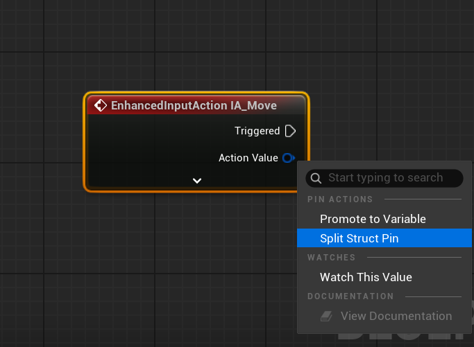
Right-click on the output pin “Action Value” of your Move Input Action and then select Split. Just like with the Look Input Action, we need the X and Y values from Axis Value.
Let’s set up the X Axis of the Input Action.
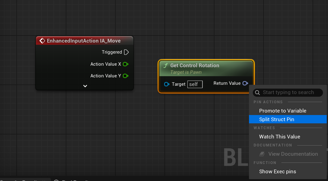
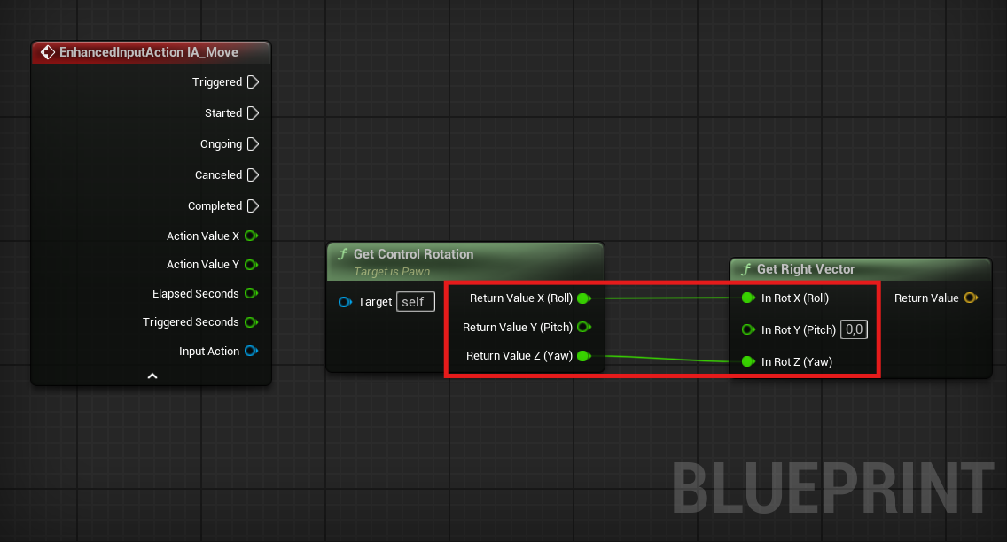
Search for the Get Control Rotation node and Split Struct its output pin. This node get the rotation of the controller, often the ‘view’ rotation of this pawn
Search for the Right Vector node and Split Struct its input pin. Then, connect the nodes as follows. Get Right Vector rotate the world right vector by the given rotation
Add the Add Movement Input node and make sure to connect your nodes as follows. Add movement input along the given world direction vector (usually normalized) scaled by ‘ScaleValue’. If ScaleValue < 0, movement will be in the opposite direction. Base Pawn classes won’t automatically apply movement, it’s up to the user to do so in a Tick event. Subclasses such as Character and DefaultPawn automatically handle this input and move.
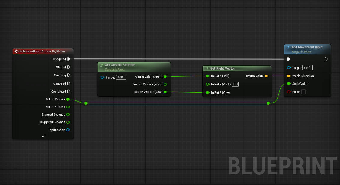
We have our left and right movement set up. Now, let’s set up forward and backward movement.
Search for the Get Control Rotation node and Split Struct its output pin. Search for the Forward Vector node and Split Struct its input pin. Rotate the world forward vector by the given rotation
Add the Add Movement Input node and make sure to connect your nodes as shown in the following image.
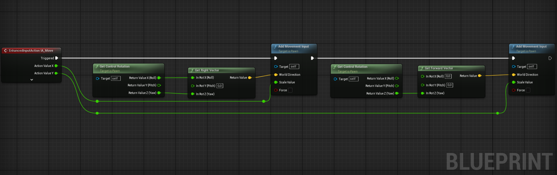
Full setup
Creation of a GameMode. Link to heading
The GameMode defines the game’s set of rules. These rules include what default pawn the player will spawn as when the game is launched. You will need to set up these rules in order to spawn the Player Character that you have created.
Option 1: Blueprint Link to heading
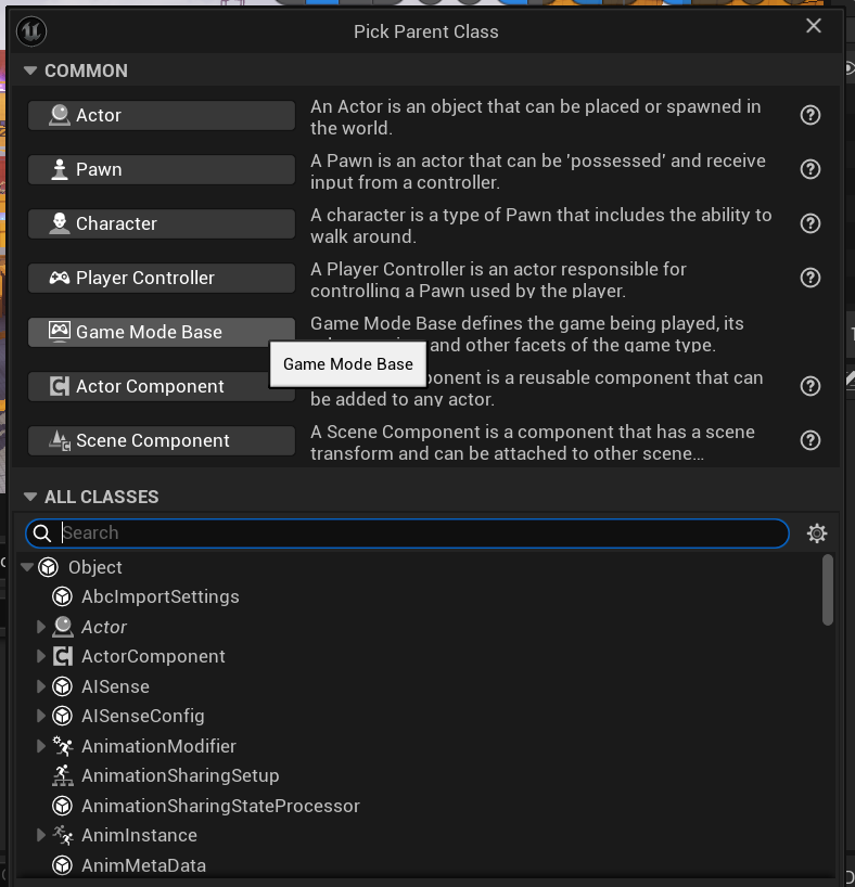
To create one, find an empty space in your Content Browser, right-click in an empty area, and select Blueprint Class.
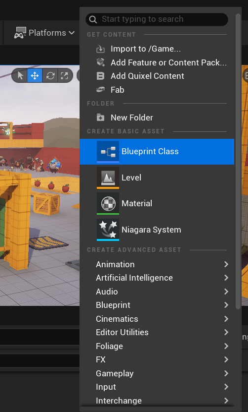
In the next window, select Game Mode Base and name it BP_GameMode
Option 2: C++ Link to heading
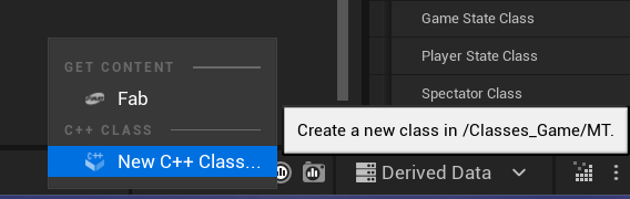
Navigate to your C++ folders and in an empty space, right-click in your Content Browser and select New C++ Class
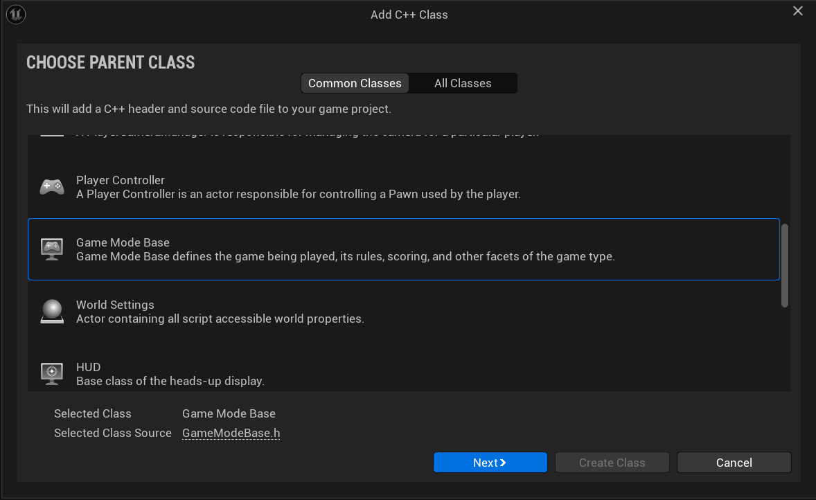
In the new window, scroll down and look for Game Mode Base. Select it and then click Next
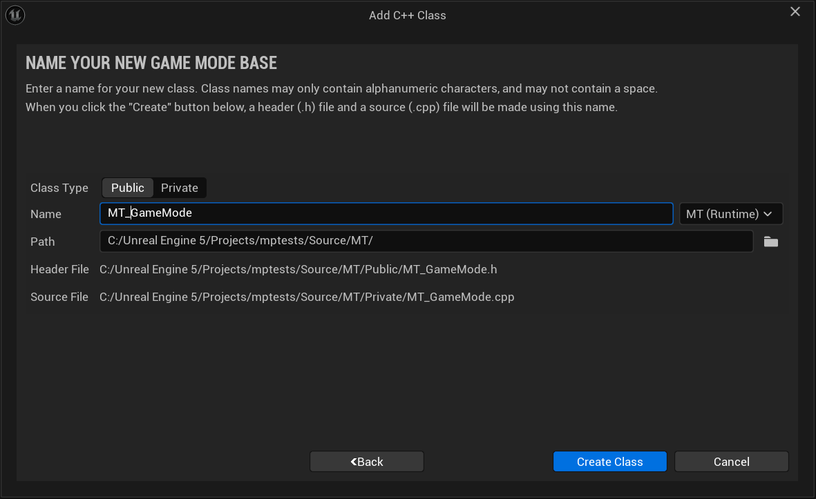
Finally, name your class and click Create Class.
Compile your code and go back to your project.
Find an empty space in your Content Browser, right-click and select Blueprint Class
In the next window, look for the C++ Class you just created, select it, and click Select. Then rename your GameMode.
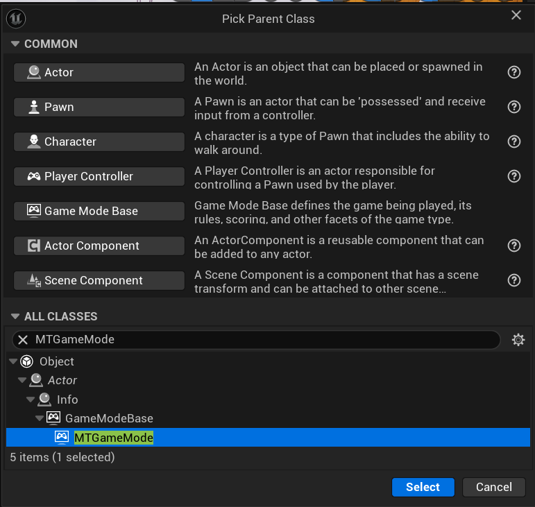
Regardless of how you created your Game Mode, now we will configure and assign it for use.
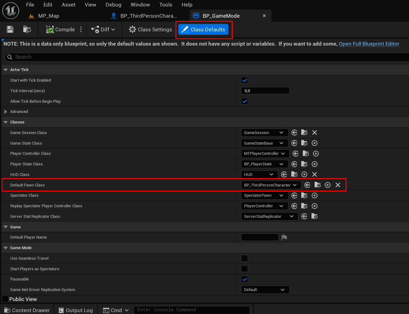
First, open your Game Mode blueprint, select Class Defaults, and look for the Default Pawn Class option in the Classes category, and place your character’s class blueprint there. Compile and save your blueprint.
Here, you can also assign things like Player Controller Class and Player State Class once you have created them.
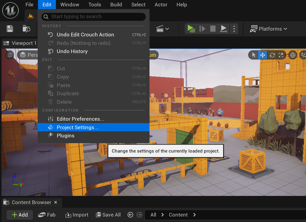
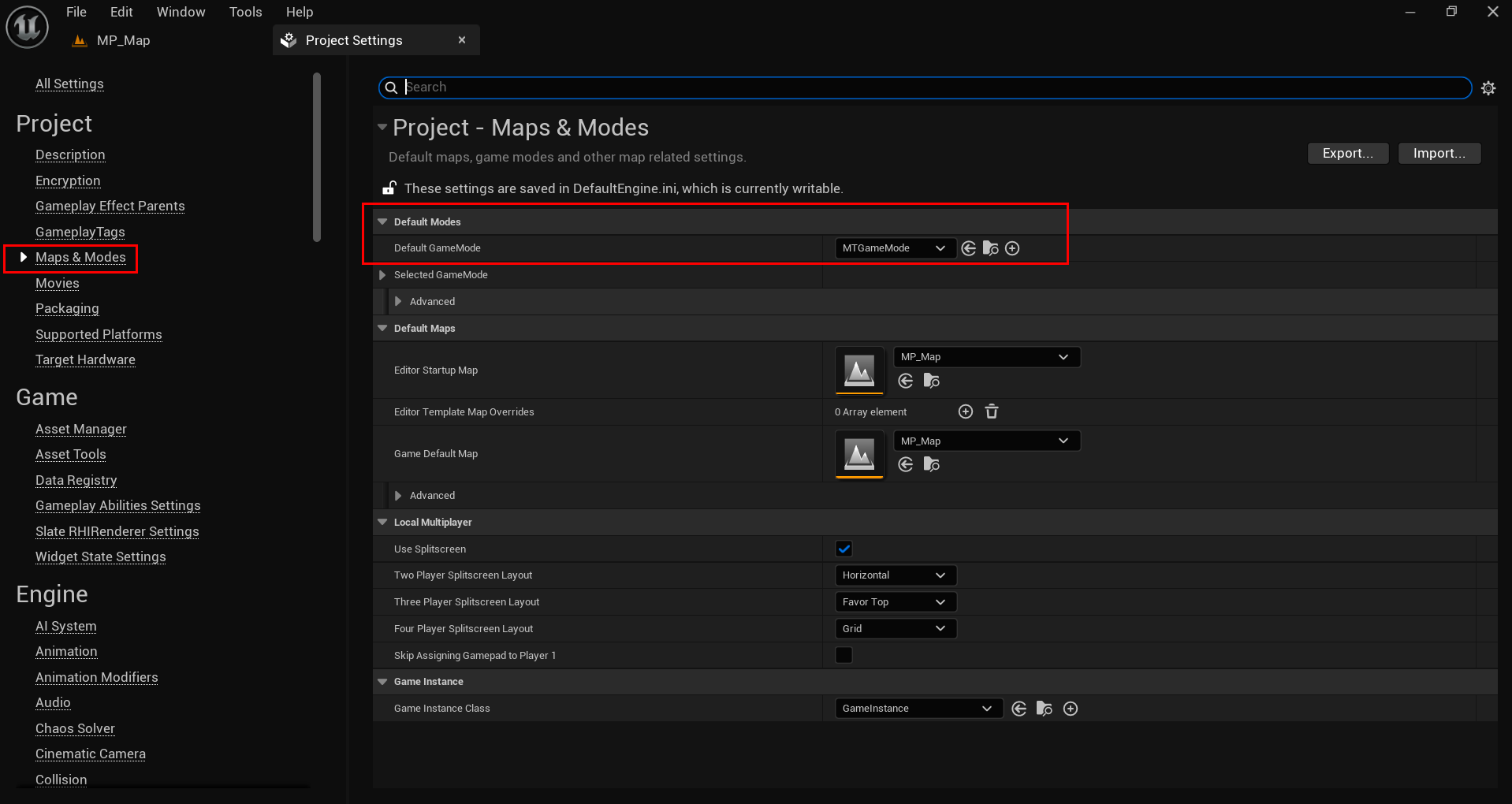
Navigate to Edit > Project Settings > Maps & Modes, and in the Default Modes category, select Bp_GameMode.
Locomotion Blend Space Link to heading
The basic functionality of your character is ready. Now let’s add animations for some of these functionalities.
Blend Spaces are special assets that allow for blending of animations based on the values of two inputs. You will create your own blend spaces that move between forward and backward and left and right movements based on the character’s movement speed or direction.
Blend Space Link to heading
You can create either a Blend Space or a Blend Space 1D (Legacy).
- Blend Space: Uses two axes (X, Y) for blending animations, ideal for complex movements like walking in different directions.
- Blend Space 1D (Legacy): Uses a single axis (X), best for simple transitions like speed changes. Less flexible than Blend Space.
Blend Space 1D (Legacy) Link to heading
To create one, find an empty space in your Content Browser, right-click in an empty area, and go to Animation > Legacy > Blend Space 1D
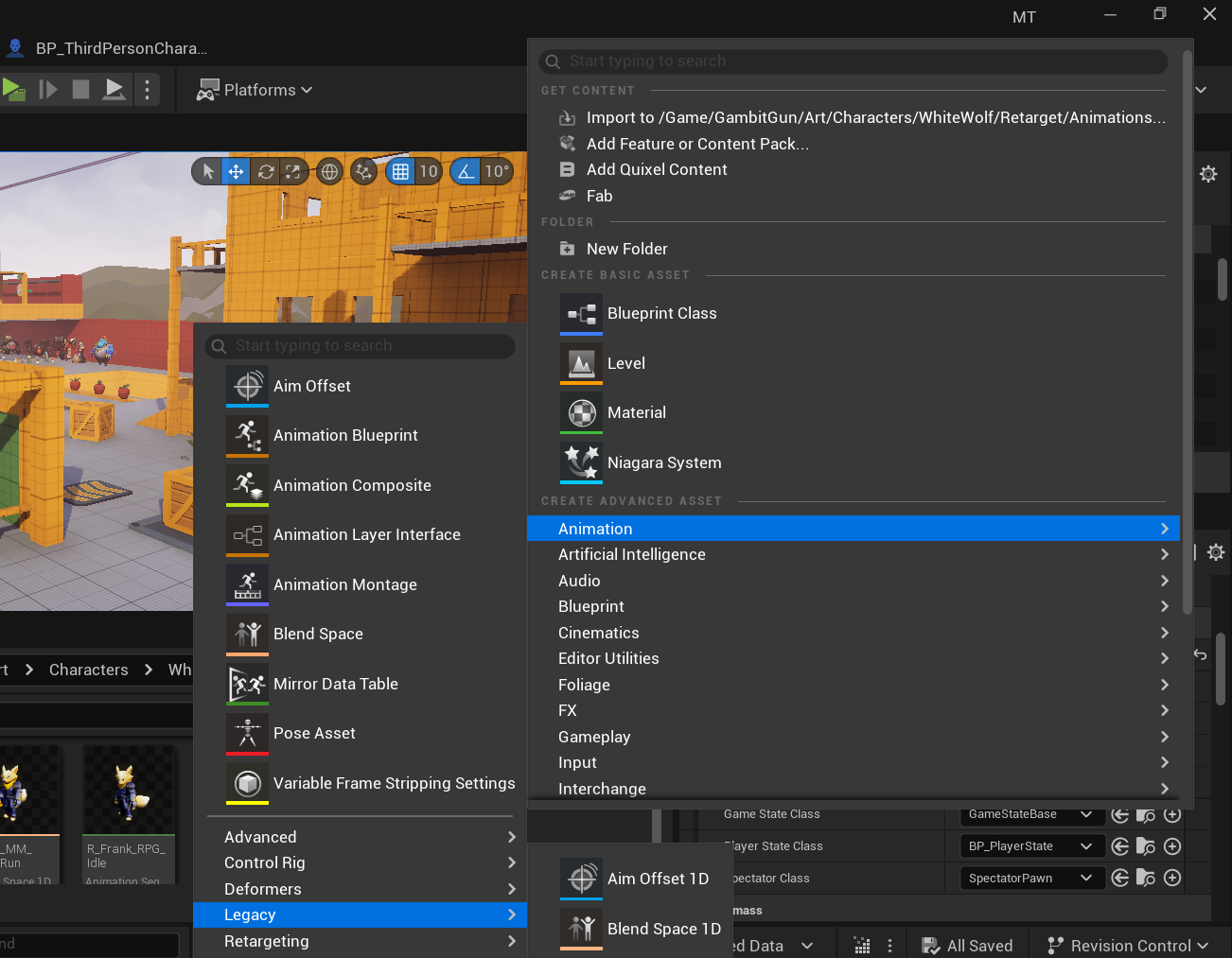
Then, select the skeleton that your character’s Skeletal Mesh uses. Click on it and then rename your Blend Space.
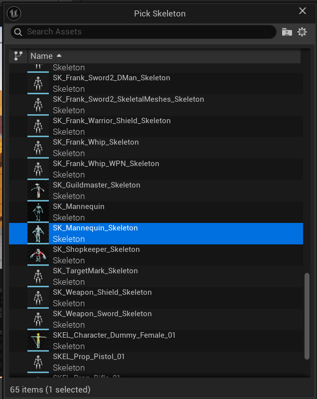
It’s important to mention that the Blend Space we created is a Blend Space 1D, meaning we’ll only work with movement animations on a single axis, the horizontal one.
Open your Blend Space and in the Asset Details panel, usually located on the left side of the screen, you’ll need to look for 3 options in the Axis Settings > Horizontal Axis category.
- Name
- Minimum Axis Value
- Maximum Axis Value
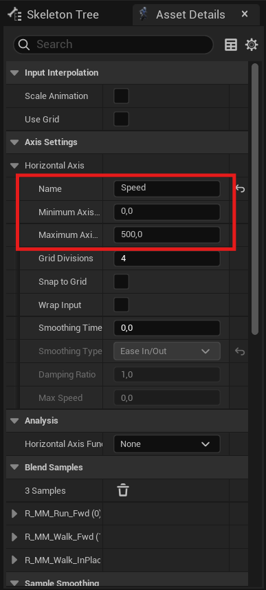
Name it Directional and set the Minimum Axis Value to 0.0 and the Maximum Axis Value to 600.0.
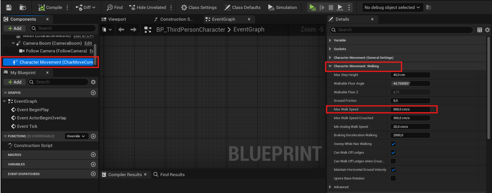
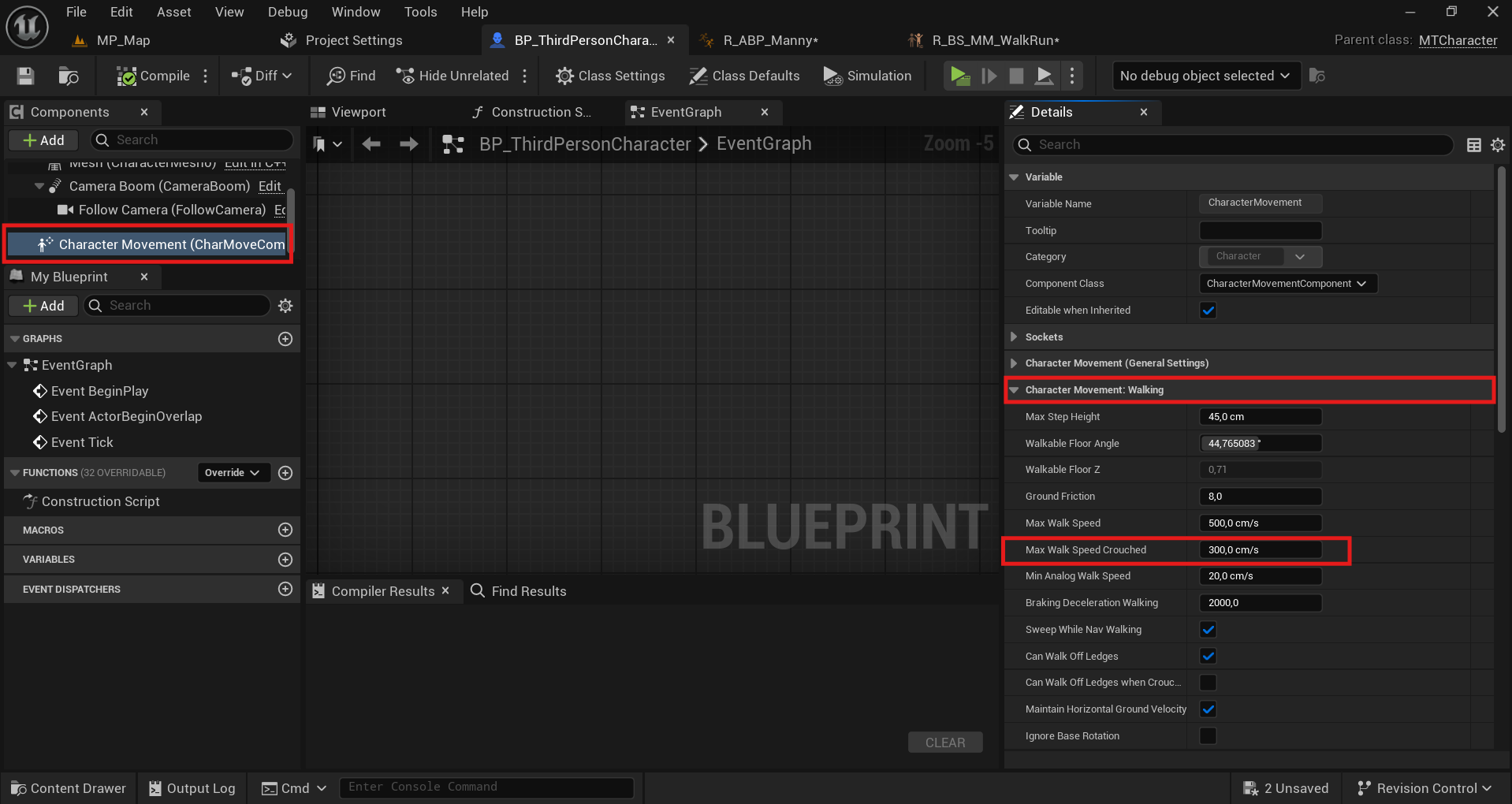
The Axis Values refer to the character’s minimum and maximum speed. By default, Character Movement has a walking speed of 600.0 cm/s in the Max Walk Speed option, which can be modified by the user. It’s important that the Maximum Axis Value matches the value of Max Walk Speed. Save the blueprint.
If you want to change or check the Max Walk Speed value, open your character’s blueprint, select the Character Movement Component, and navigate to the Character Movement: Walking category.
Back to the Blend Space 1D. On your screen, you should have something like the image below.
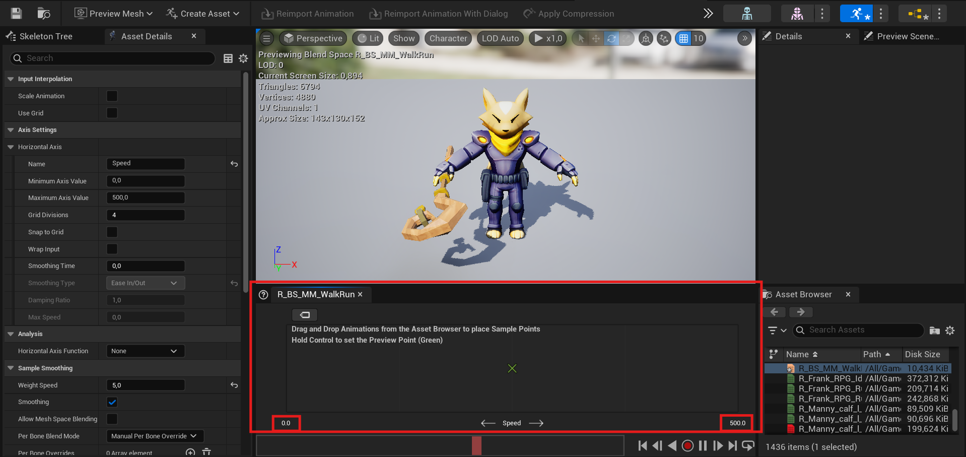
In the red box, there’s a space where we will place the corresponding animations for our character in an organized manner. In the image, you can see that on the left side of the panel, at the bottom, there’s a value: 0.0. On the right side, at the bottom, there’s another value: 600.0. These values are what you assigned in Minimum Axis Value and Maximum Axis Value.
What we will do is, in the Asset Browser panel on the right, search for your character’s Idle animation and place it on the left side. This means a blend will happen towards the Idle animation when the character’s speed drops to 0.
If you have animations like Walk in Place, they can also be used instead of the Idle animation.

Let’s do the same with your character’s Walk and Run animations. Drag the Walk animation to the center of the animation panel and the Run animation to the right of the panel. If you want to position the animations precisely to the left, center, and right of the animation panel, simply drag the animations to those positions while holding Shift, and it will activate snapping.
If you move your mouse while holding Left Ctrl over the panel where you placed the animations, you will see a cross that moves from left to right, simulating the character’s speed. In the viewport at the top, where the character is displayed, you will see the blend of the animations in more detail.

Crouch Blend Space 1D (Legacy) Link to heading
Let’s repeat the steps to create a new Blend Space 1D, which will be used for moving the character while in a crouch.
You can create a new one or duplicate the Blend Space you just created and replace the Idle, Walk, and Run animations with Idle Crouch and Walk Crouch. For crouch, 3 animations are required.

Also, replace the Maximum Axis Value with the Max Walk Speed Crouched value. You can find this value in the Character Movement Component assigned in your character’s blueprint under the Character Movement: Walking category.
Blend Space Link to heading
To create one, find an empty space in your Content Browser, right-click in an empty area, and go to Animation > Blend Space
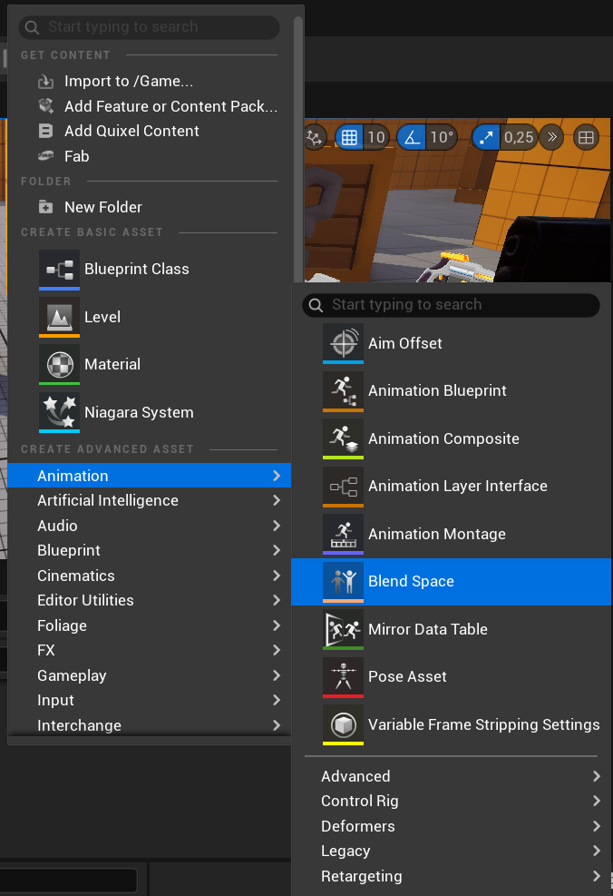
Then, select the skeleton that your character’s Skeletal Mesh uses. Click on it and then rename your Blend Space.
Open your Locomotion.
In the Asset Details tab, navigate to the Axis Settings category, then select the arrows adjacent to the Horizontal Axis and the Vertical Axis to see more variable details.
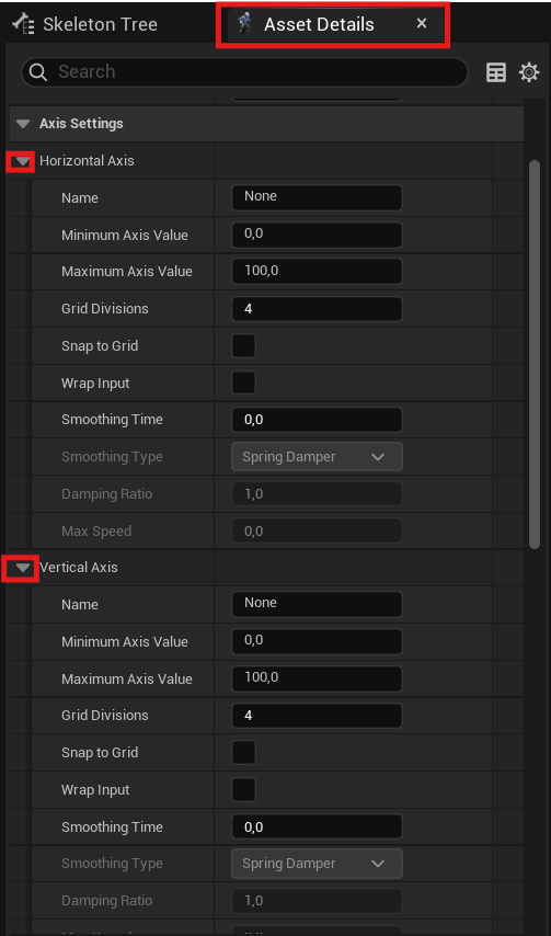
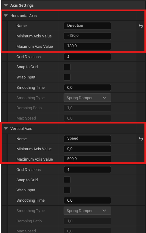
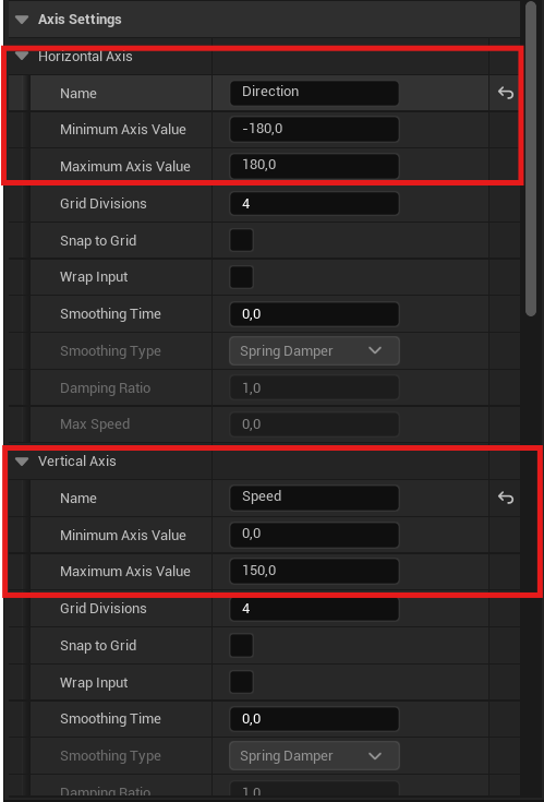
In the Horizontal Axis settings, change the Name variable to Direction, then set the Minimum Axis Value to -180, and the Maximum Axis Value to 180.
In the Vertical Axis Settings, change the Name variable to Speed, then set the Maximum Axis Value to the Max Walk Speed of your character.
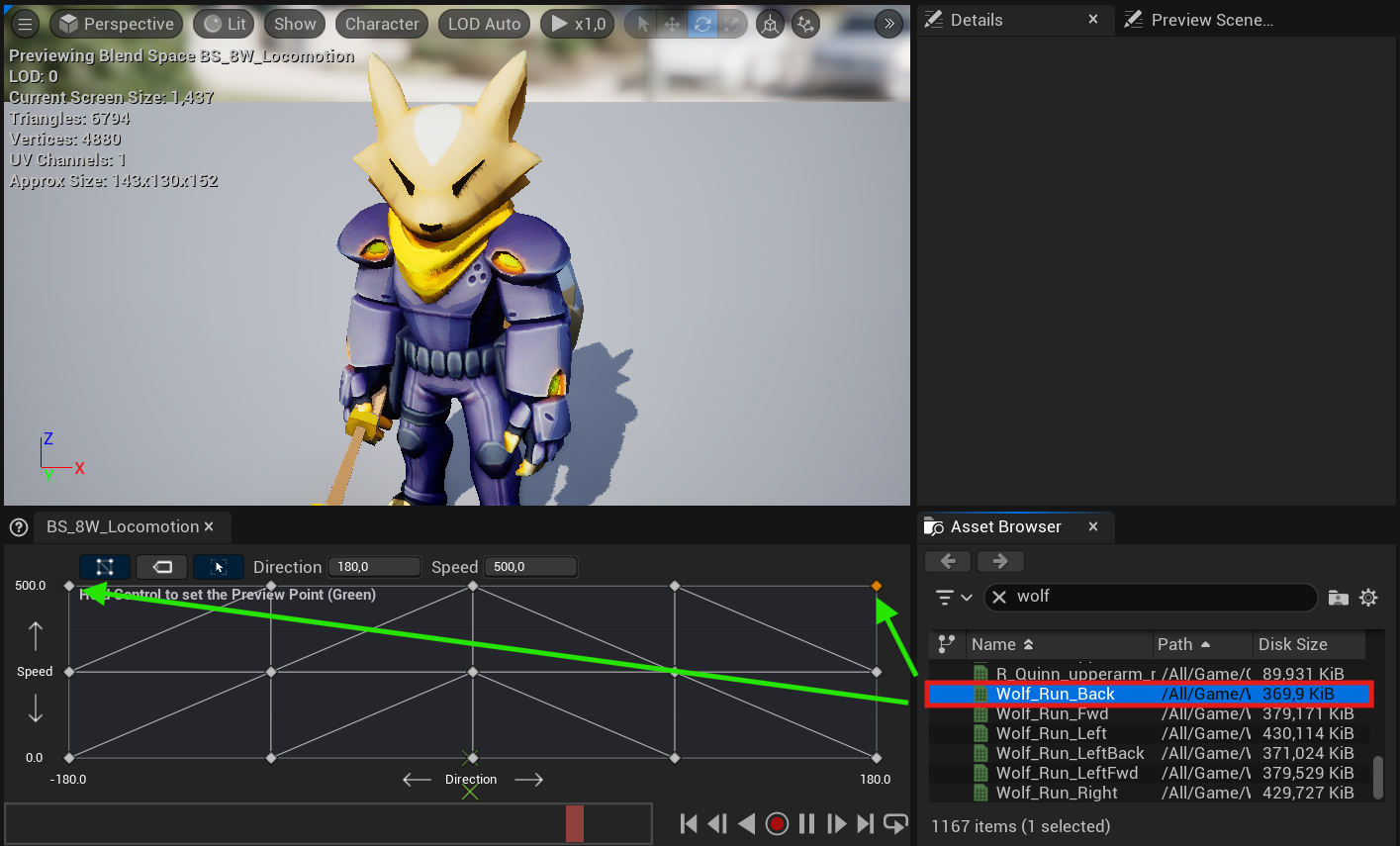
Navigate to the Asset Browser, then within the filters search bar type the Idle animation for your character, then drag and drop the Idle Animation asset into the Blend Space at Direction 0.0, and Speed 0.0.

Repeat the previous step, inserting the Idle Animation asset into: Direction 180, Speed 0. Direction 90, Speed 0. Direction -90, Speed 0. Direction -180, Speed 0.

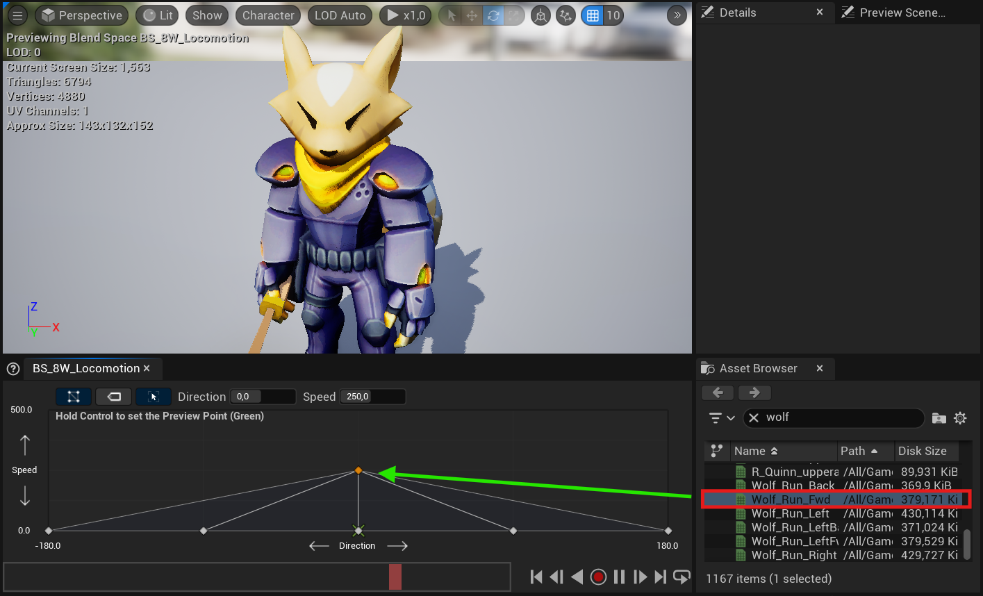
In the Asset Browser tab Filters search bar type your Walk/Run Forward Animation, then drag and drop the Walk/Run Forward Animation asset into the Blend Space at Direction 0.0, and half Speed.
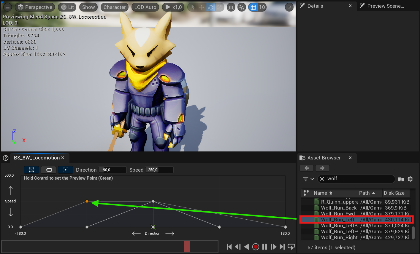
Next, in the Asset Browser tab Filters search bar type your Left Walk/Run Animation, then drag and drop the Left Walk/Run Animation asset into the Blend Space at Direction -90 and half Speed.
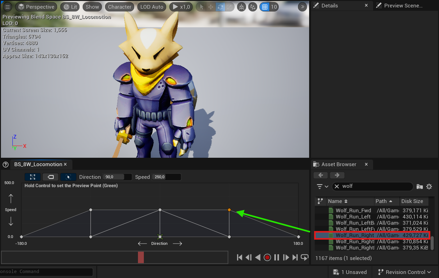
In the Asset Browser tab Filters search bar type your Right Walk/Run Animation, then drag and drop the Right Walk/Run Animation asset into the Blend Space at Direction 90 and half Speed.
In the Asset Browser tab Filters search bar type your Walk Backward Animation, then drag and drop the Walk Backward Animation asset into the Blend Space at Direction 180 and half Speed, then drag and drop it again at Direction -180 and half Speed.
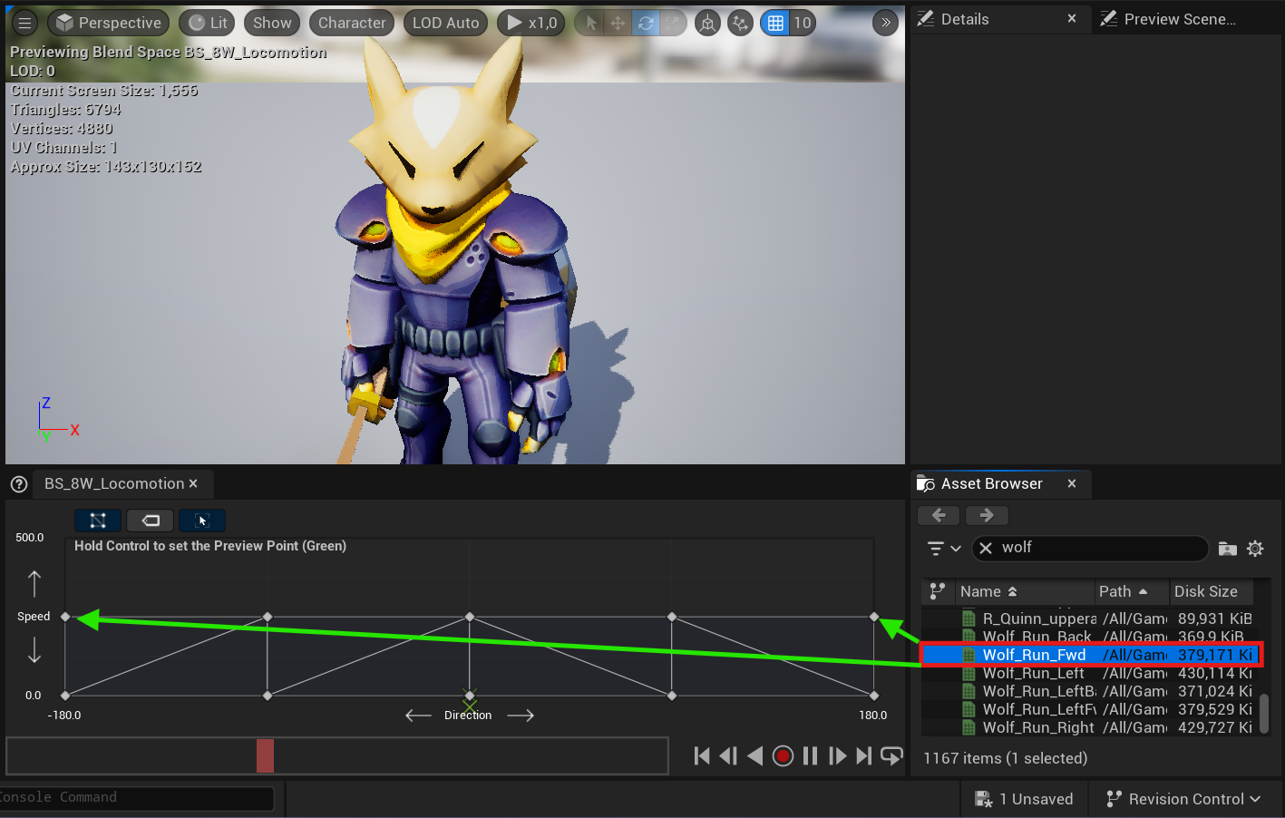
In the Asset Browser tab Filters search bar type your Walk/Run Forward / Jog Walk/Run Forward Animation, then drag and drop the Walk/Run Forward / Jog Walk/Run Forward Animation asset into the Blend Space at Direction 0.0, and maximum Speed.
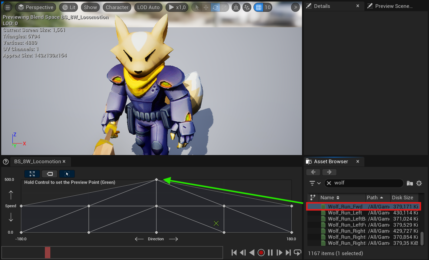
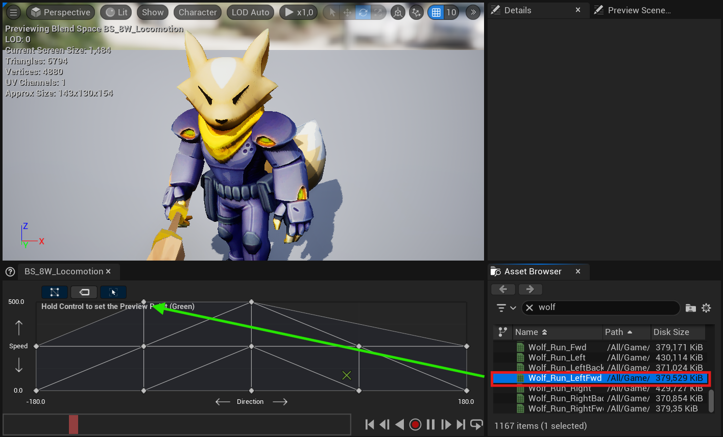
Navigate to the Asset Browser, then within the filters search bar type your Jog Left, then drag and drop the Jog Left asset into the Blend Space at Direction -90, and maximum Speed.
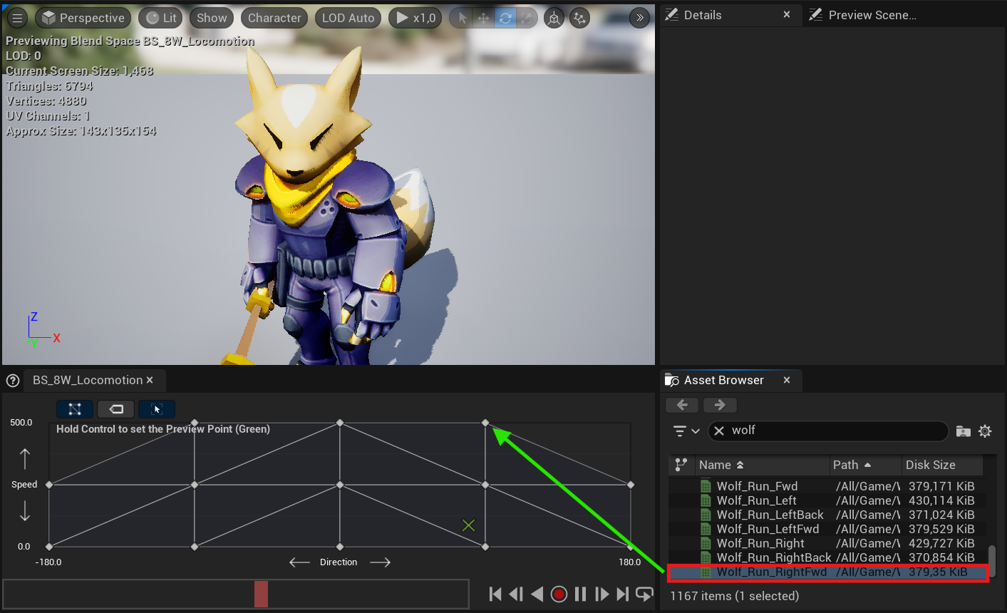
Navigate to the Asset Browser, then within the filters search bar type Jog Right, then drag and drop the Jog Right asset into the Blend Space at Direction 90, and maximum Speed.
From the asset browser search bar filter type Walk Backward Animation, then drag and drop an Walk Backward Animation asset into the Blend Space at Direction 180 and maximum Speed, then drag an additional Walk Backward Animation at Direction -180 and maximum Speed.
Crouch Blend Space Link to heading
Let’s repeat the steps to create a new Blend Space, which will be used for moving the character while in a crouch.
Change the values for Vertical Axis. In “Maximum Axis Value”, set your Max Walk Speed Crouched value. The values for Horizontal Axis remain the same as in the previous Blend Space, as shown in the following image.
Repeat the previous steps from the Blend Space section.
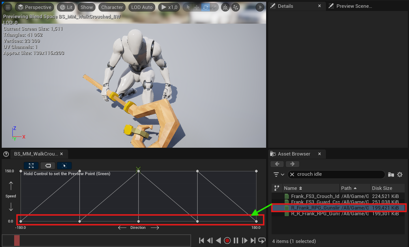
Place your Idle Crouch Animation as shown in the image. Crouch Idle Animation → Speed: 0, Direction: 0, 90, -90, 180, -180
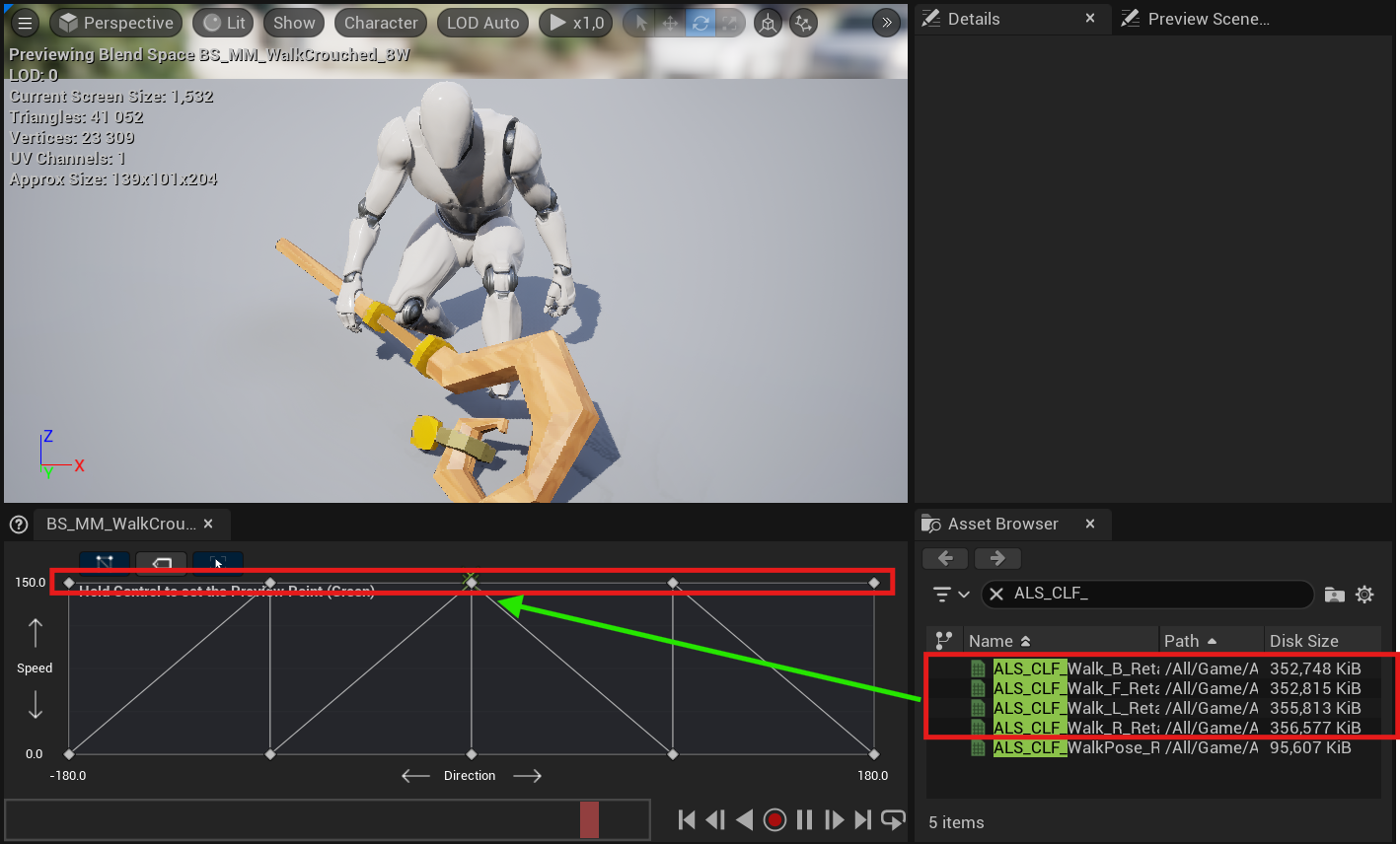
Then do the same for the other animations.
Crouch Forward Animation → Speed: (Your Maximum Axis Value), Direction: 0
Crouch Left Animation → Speed: (Your Maximum Axis Value), Direction: -90
Crouch Right Animation → Speed: (Your Maximum Axis Value), Direction: 90
Crouch Backward Animation → Speed: (Your Maximum Axis Value), Direction: 180, -180
Animation Blueprint Link to heading
When you have created your Blend Space or Blend Space 1D, you can continue with the creation of an Animation Blueprint.
You will require an Animation Blueprint that will determine what character animations to play based on the current actions by the player. Additionally, you will need to set up a State Machine to create a Walk and Crouch state, then set up the transitions between each of them.
In your Animation Blueprint, there will be some differences depending on whether you use a Blend Space or a Blend Space 1D (Legacy).
In an empty space of your Content Browser, right-click and select Animation > Animation Blueprint.
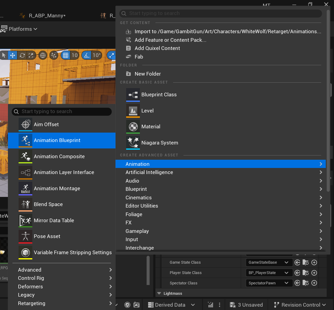
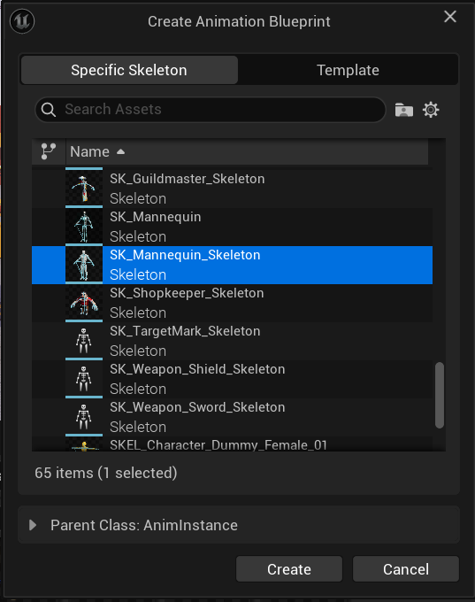
After creating it, select the Skeleton corresponding to your character’s Skeletal Mesh and then click on Create. Once created, rename it.
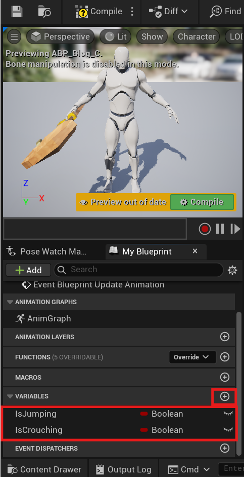
Double-click your Animation Blueprint to open it. In the My Blueprint tab, navigate to the Variables category and select the adjacent + sign to create two boolean variables named IsCrouched and IsJumping.
Click the Event Graph tab, then drag off from the Return Value pin of the Try Get Pawn Owner node. From the dropdown menu, search for and select your Character Cast node.
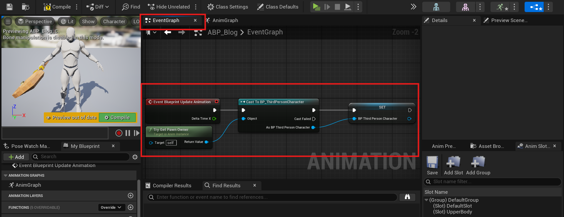
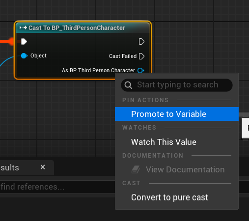
Then, right-click on the As BP Your Class Name pin located at the bottom right of your Character Cast Node and select the Promote to Variable option. Rename it to BP Character.
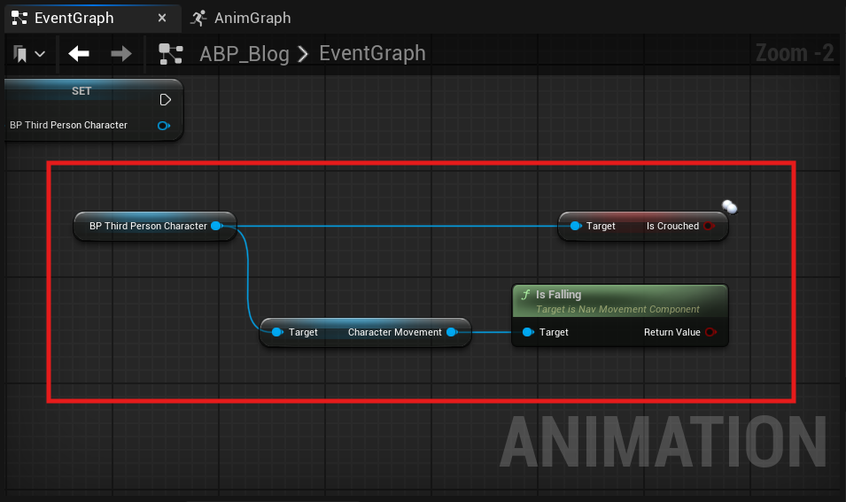
Drag your BP Character variable into the event graph while holding the Left Ctrl key to use the Get of your variable. Then, drag off from the BP Character variable return pin and search for these two variables: Get IsCrouched and Get CharacterMovement. Drag off from the CharacterMovement return pin and search for IsFalling.
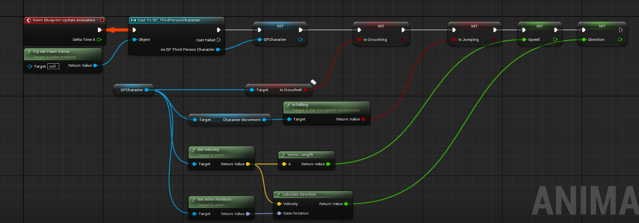
Now, hold Alt and drag the variables you created in the Animation Blueprint to the Event Graph, IsCrouching and IsJumping, to get the Set of the variables and pass the values of IsCrouched and IsFalling. Make sure everything is connected as shown below:
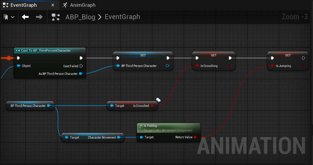
Compile and Save your Animation Blueprint.
In your Animation Blueprint from the Variables category select the adjacent + sign to create a float variable named Speed.
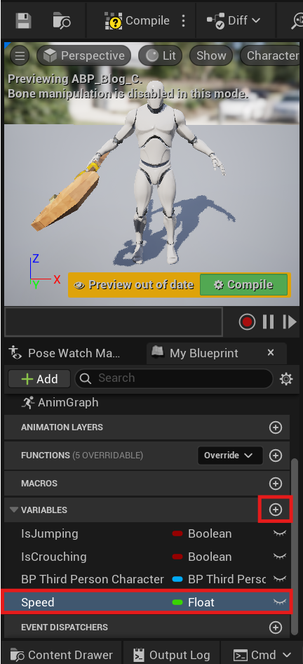
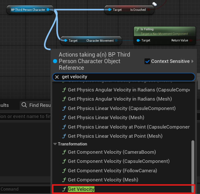
Drag off from the BP Character variable return pin, then click to enable the context sensitive box, and search for and select Get Velocity.
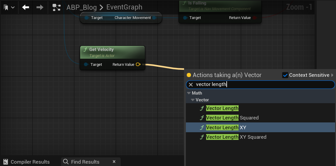
Drag off from the Get Velocity node’s Return Value pin, and from the Actions drop down menu, search for and select Vector Length XY.
Finally connect Vector Length XY to the set of the ‘Speed’ variable as shown below.
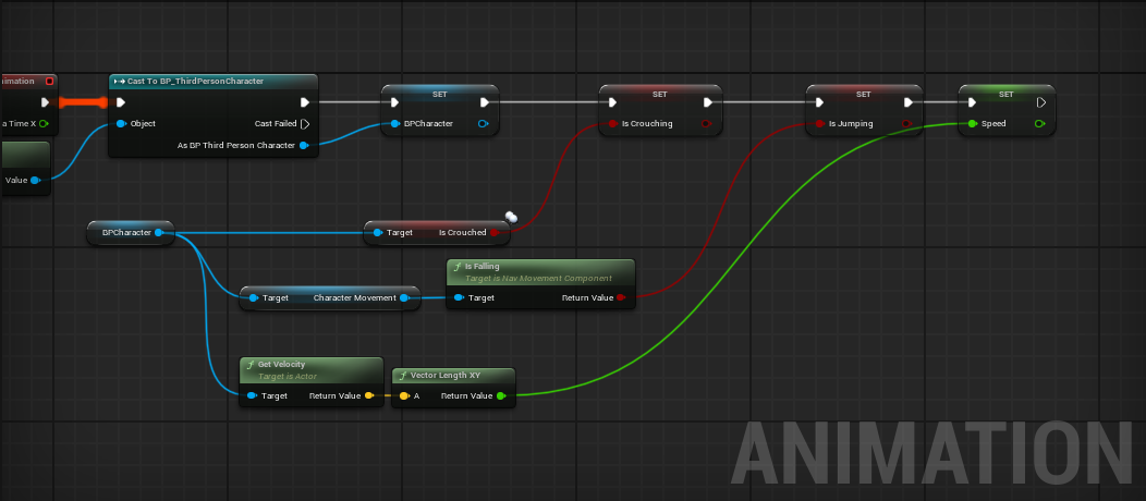
Compile and Save your Animation Blueprint.
If you used Blend Space instead of Blend Space 1D (Legacy) Link to heading
Replace your Vector Length XY and use the Vector Length node instead.
Drag off from the BP Character variable and search for Get Actor Rotation node. Then drag off Get Velocity Output pin and search for Calculate Direction node. Also, connect the output pin of Actor Rotation to the Base Rotation input pin of the Calculate Direction node.
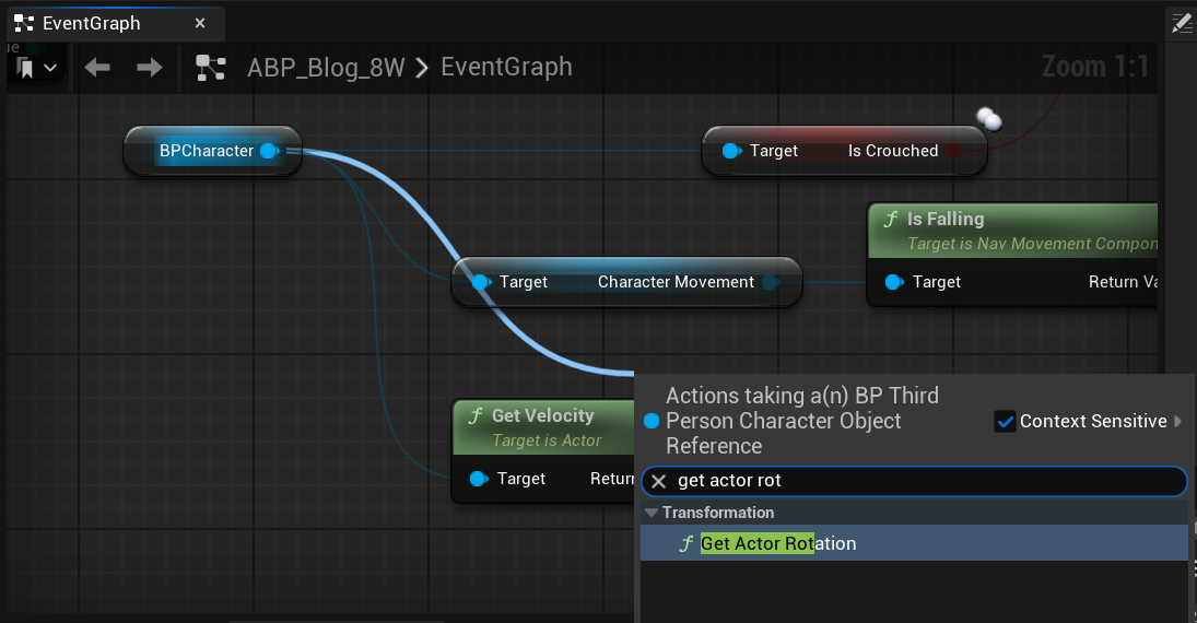
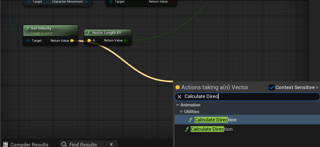
Then right-click the Calculate Direction Output pin and select promote to variable. Finally, make sure everything is connected as shown in the following image.
Animation State Machine Link to heading
State Machines provide a graphical visualization of organizing the animation of a Skeletal Mesh into a series of States. These states are governed by Transition Rules that control how to blend from one state to another. You will use your boolean variables to transition between the different locomotion Blend Spaces that you created in the earlier sections.
Inside your Animation Blueprint, navigate to the Anim Graph.
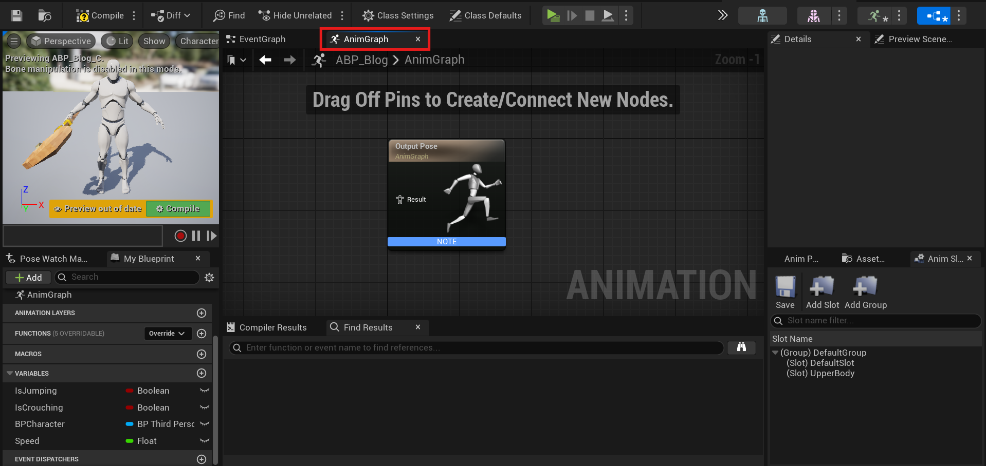
The AnimGraph is used to evaluate a final pose for the skeletal mesh.
Right-click on the AnimGraph and from the Actions drop down menu, search for and select Add New State Machine.
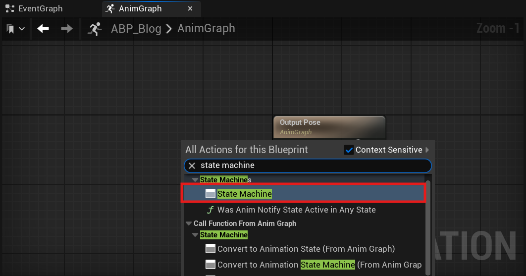
Rename your State Machine node to Locomotion, then double-click the node to open its graph. Drag off from the Entry pin, and from the Actions drop down menu, select Add State.
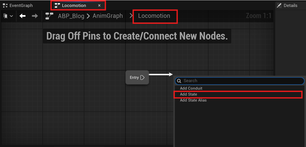
Name the new state Movement, then double-click to open the Movement State Node.
Navigate to the Asset Browser and search for the Walk Blend Space you previously created. Click and drag it into the graph.
Connect the Get node of your Speed variable to the corresponding input node of the Blend Space, and then connect the Blend Space to the Output Animation Pose.
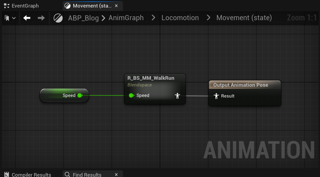
If you used Blend Space instead of Blend Space 1D (Legacy) Link to heading
Also, connect the Get node of your Direction variable to the corresponding input node of the Blend Space.
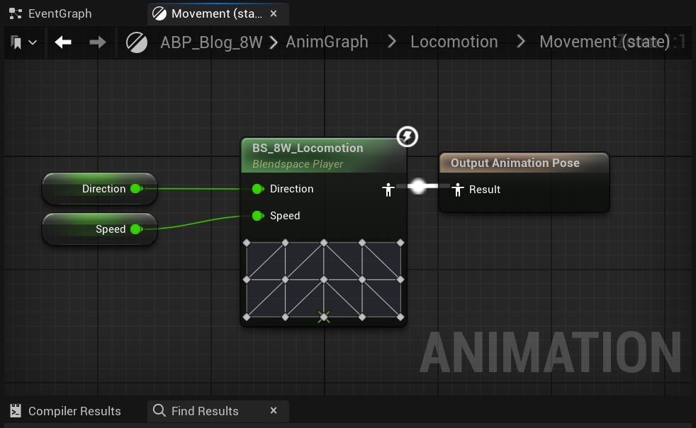
Compile and Save your Animation Blueprint.
Crouched State Link to heading
Navigate back to the Locomotion state machine, then click and drag the Movement state node to create a new Animation state named Crouch Movement.
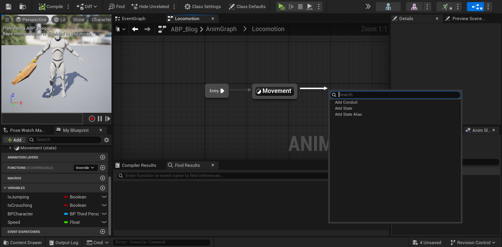
Double click the Transition rule node to open its Anim Graph.
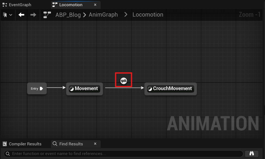
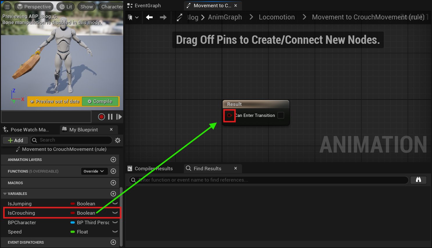
From the My Blueprint Tab, navigate to the variables category and drag your Is Crouched boolean onto the Can Enter Transition input pin from the Result node.
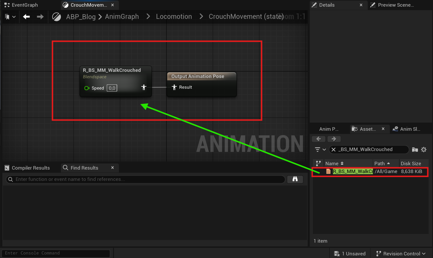
Navigate back to the Locomotion state machine graph, and double click on the Crouch Movement state to open its anim graph. From the Asset browser, search for your Crouch Blend Space, then click and drag it into the graph.
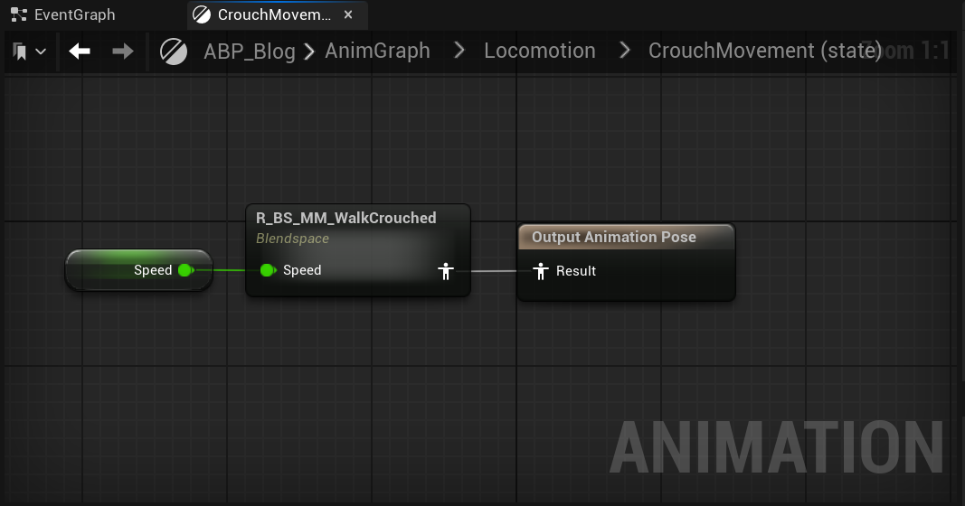
From the My Blueprint Tab, navigate to the variables category and drag your Speed and Direction float variables into their respective pins on the Crouch Blend Space, then connect your Crouch Blend Space Animation Pose into your Output Animation Pose Result pin.
Navigate back to the Locomotion AnimGraph then click and drag off the CrouchMovement Animation state and connect it to the Movement Animation State.
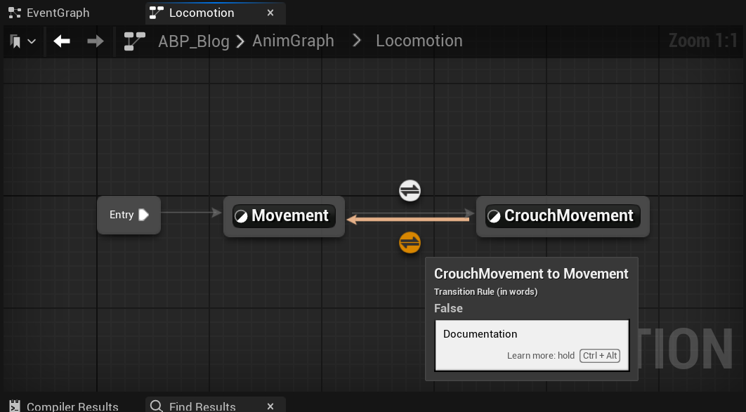
Double click the Transition rule node to open it’s Anim Graph.
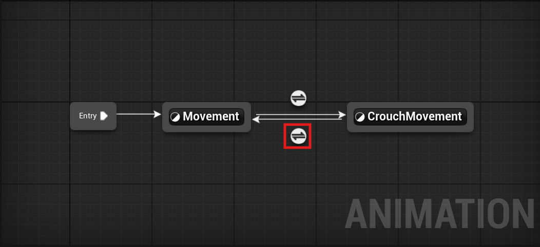
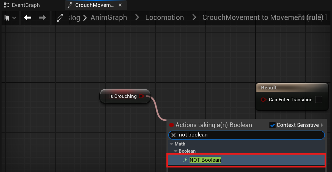
From the My Blueprints tab, click and drag the IsCrouched boolean variable onto the Anim Graph, select Get IsCrouched, then drag off from its output pin and in the drop down actions menu search for and select NOT Boolean.
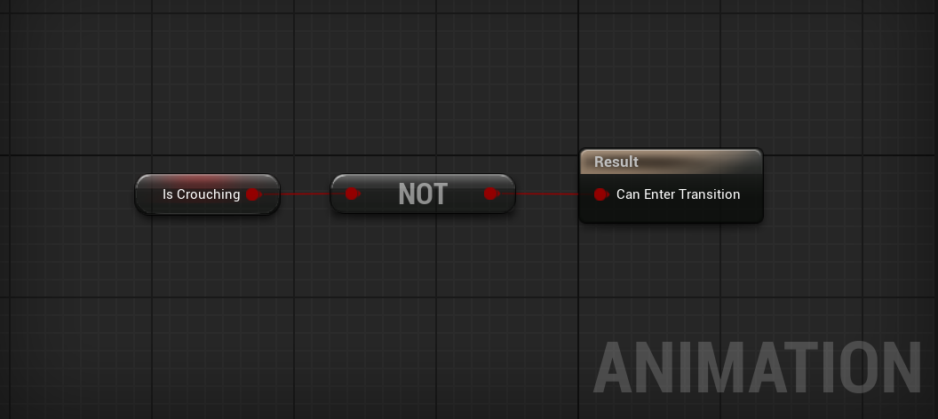
Next, connect the NOT Boolean’s return pin to the Can Enter Transition input pin.
If you used Blend Space instead of Blend Space 1D (Legacy) Link to heading
Also, connect the Get node of your Direction variable to the corresponding input node of the Blend Space.
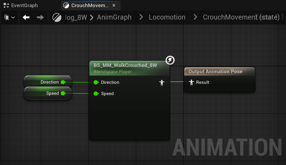
Compile and Save your Animation Blueprint.
Jump State Link to heading
Navigate back to the Anim Graph, then click and drag off from the Movement Animation state and select Add State.
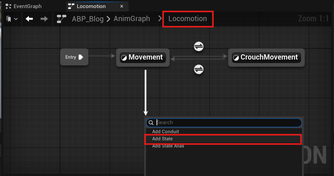
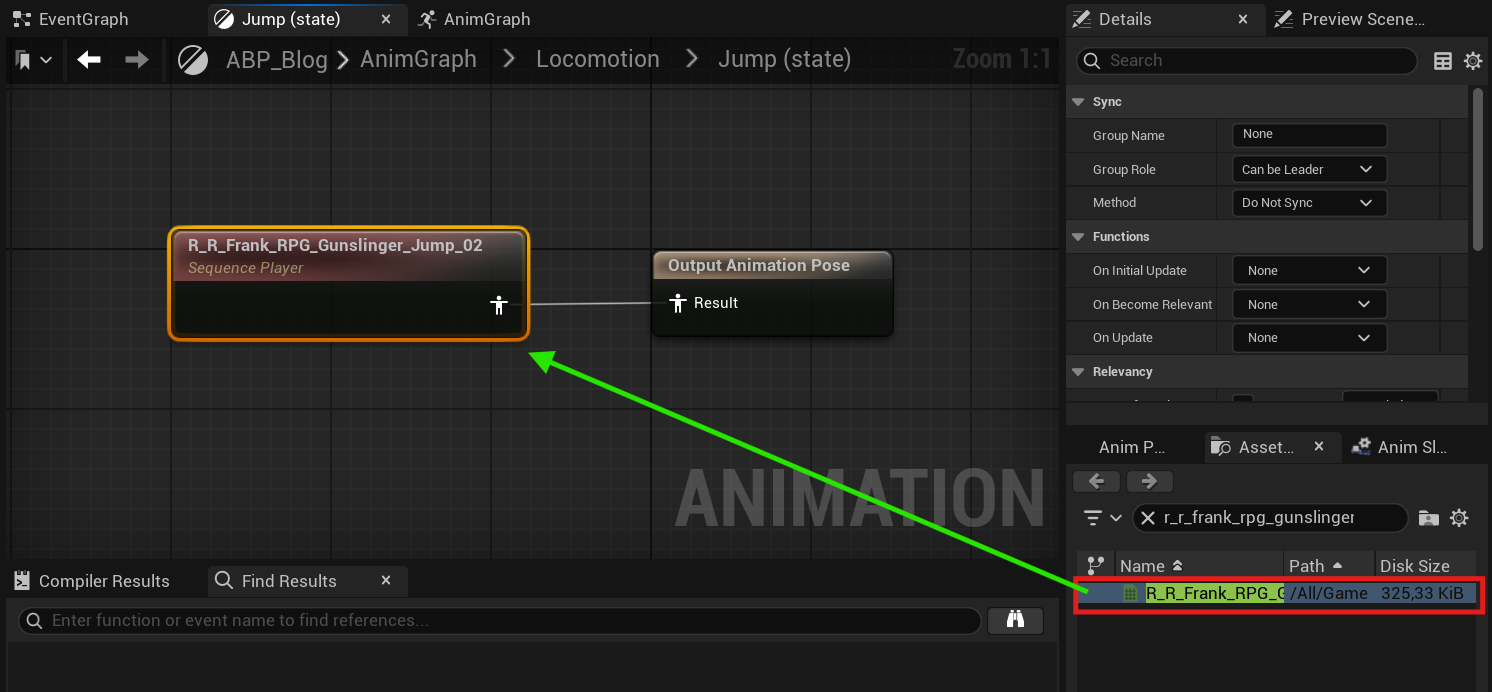
Rename this Animation State to Jump, then double-click to open its animation graph. Navigate to the Asset Browser and search for your Jump animation, then drag it into the graph. Finish your Jump Animation State by connecting your Jump Animation Pose to your Output Animation Pose Result pin.
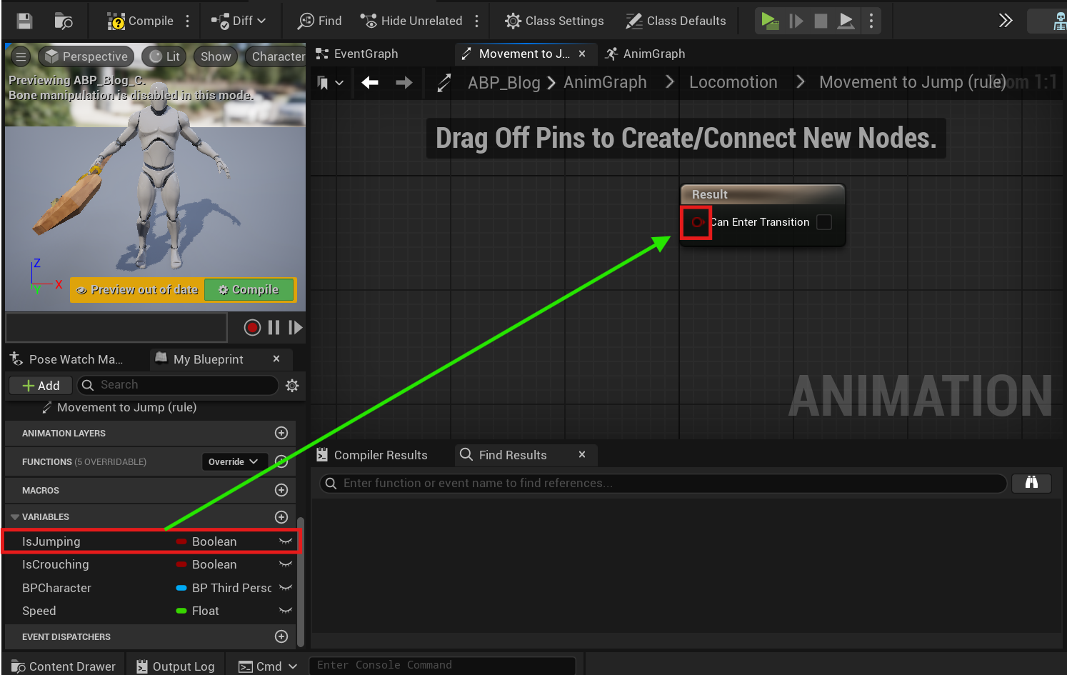
Navigate back to the Locomotion Anim Graph, then double-click the Movement to Jump Transition rule node to open its Anim Graph.
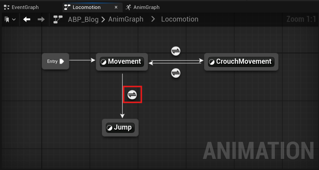
Inside the Transition Rule Anim Graph, navigate to the My Blueprints tab, and drag your Is Jumping Boolean variable onto the Result node’s Can Enter Transition input pin.
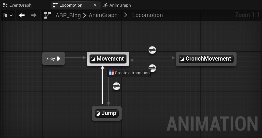
Navigate back to the Locomotion Anim Graph, then click and drag off the Jump anim node and create a transition to the Movement Anim Graph node.
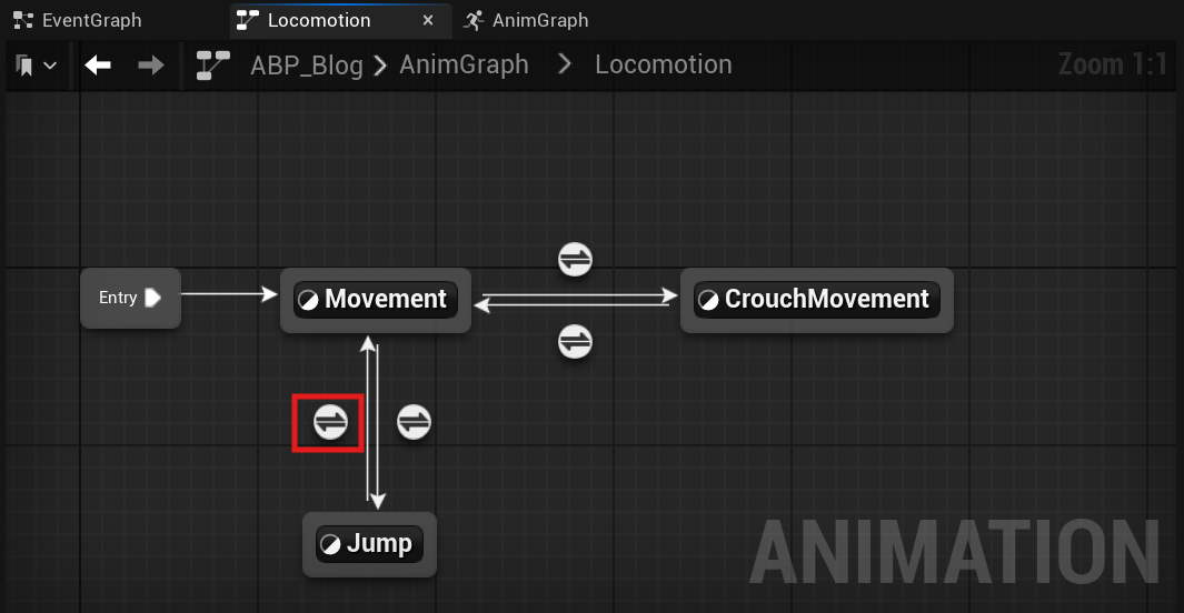
Double-click the Jump to Movement Transition rule node to open it’s Anim Graph.
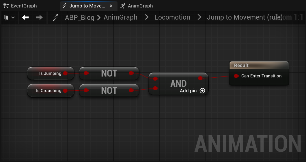
From the My Blueprints tab, click and drag the IsCrouched, and IsJumping Boolean variable onto the Anim Graph, then drag off each of their output pins and from the drop down actions menu search for and select NOT Boolean. Then drag off the NOT Boolean output pin and search for and select for the AND Boolean. Connect both the IsCrouched, and IsJumping NOT Boolean node output pins into the AND Boolean node’s input pins, then connect the AND boolean’s output pin into the Result node’s Can Enter Transition Input pin.
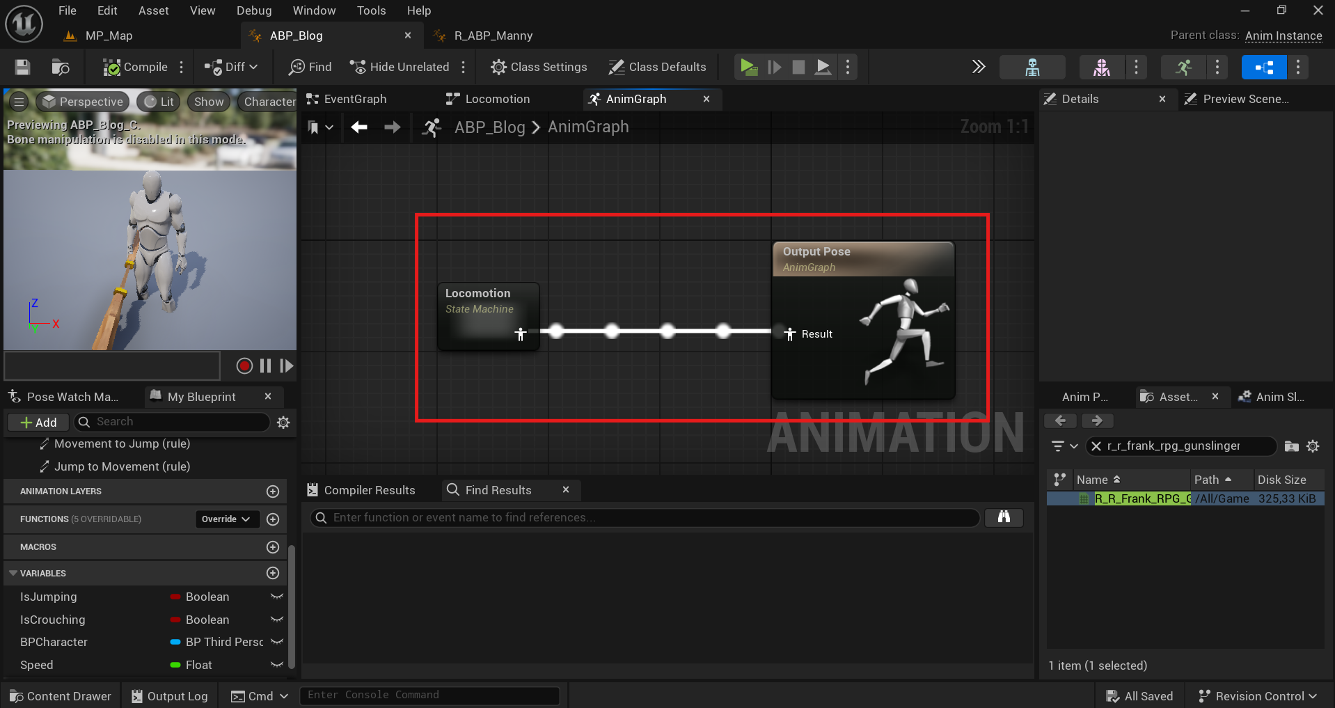
Navigate to the AnimGraph and connect the Locomotion Pose Output pin into the Output Pose Result pin. Then Compile and Save your Animation Blueprint.
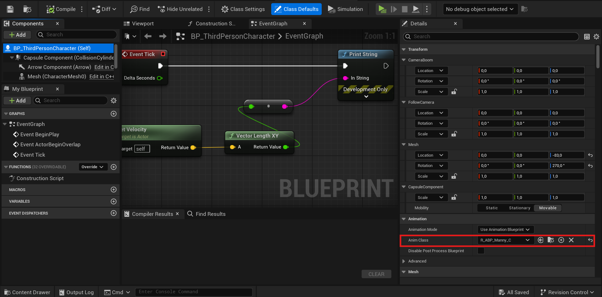
From the Content Browser, open your Character’s blueprint, then in the Components tab select the Mesh component, then navigate to the Details panel Animation category and in the Anim Class variable drop down menu, search for and select your Animation Blueprint.
Binding character movement to GAS Link to heading
In case you want to bind your character movement to GAS it’s recommeded to read the section about GAS You can bind attributes to modify your character movement component and create effects like speed modifiers or jump platforms. To exemplify it we are going to create an attribute called Speed in your AttributeSet.
UPROPERTY(ReplicatedUsing = OnRep_Speed, BlueprintReadOnly)
FGameplayAttributeData Speed;
ATTRIBUTE_ACCESSORS(UMTAttributeSet, Speed)

UFUNCTION()
void OnRep_Speed(const FGameplayAttributeData& OldSpeed);
You can bind a function in the PossessedBy method of your character to handle changes to your Speed attribute. Use the GetGameplayAttributeValueChangeDelegate from your Ability System Component to obtain the delegate and bind the function.
void AMTCharacter::PossessedBy(AController* NewController)
{
	Super::PossessedBy(NewController);

	if(AMTPlayerState* MTPlayerState = Cast<AMTPlayerState>(GetPlayerState()))
	{
		if(MTPlayerState->AbilitySystemComponent)
		{
			MTPlayerState->AbilitySystemComponent->InitAbilityActorInfo(MTPlayerState, this);
			AbilitySystemComponent = MTPlayerState->AbilitySystemComponent;
			AttributeSet = MTPlayerState->AttributeSet;

			if(UMTAttributeSet* MTAttributeSet = Cast<UMTAttributeSet>(AttributeSet))
				AbilitySystemComponent->GetGameplayAttributeValueChangeDelegate(MTAttributeSet->GetSpeedAttribute()).AddUObject(this,  &AMTCharacter::UpdateCharacterSpeed);

		}
	}
void AMTCharacter::UpdateCharacterSpeed(const FOnAttributeChangeData& Data)
{
	GetCharacterMovement()->MaxWalkSpeed = Data.NewValue;
}
The delegate will allow you to keep your MaxWalkSpeed with the same value as Speed attribute in the server, but you will have to update it in the client too. You can update the value for the client inside your AttributeSet class using the funcion OnRep_Speed previously declared.
void UMTAttributeSet::OnRep_Speed(const FGameplayAttributeData& OldSpeed)
{
	GAMEPLAYATTRIBUTE_REPNOTIFY(UMTAttributeSet, Speed, OldSpeed);
	if(AMTCharacter* Character = Cast<AMTCharacter>(GetActorInfo()->AvatarActor))
		Character->GetCharacterMovement()->MaxWalkSpeed = Speed.GetCurrentValue();
}
If you used Blend Space instead of Blend Space 1D (Legacy) Link to heading
In your BP Character, select the Character and set true “Use Controller Rotation Yaw”.
Then select the Character Movement Component and search for “Orient Rotation to Movement” and make sure is set to false.
Final Result Link to heading
From the toolbar select Play (PIE), you will be able to control your character’s movement using the asigned keys.
Blend Space 1D (Legacy)

Blend Space

References Link to heading
Setting Up Character Movement | Unreal Engine 5.5 Documentation | Epic Developer Community. (2024). Epic Games Developer. https://dev.epicgames.com/documentation/en-us/unreal-engine/setting-up-character-movement
Enhanced Input in Unreal Engine | Unreal Engine 5.5 Documentation | Epic Developer Community. (2024). Epic Games Developer. https://dev.epicgames.com/documentation/en-us/unreal-engine/enhanced-input-in-unreal-engine